Analog Modules
4-166
Programmable Logic Controllers S7-300 Module Data
A5E00105505-03
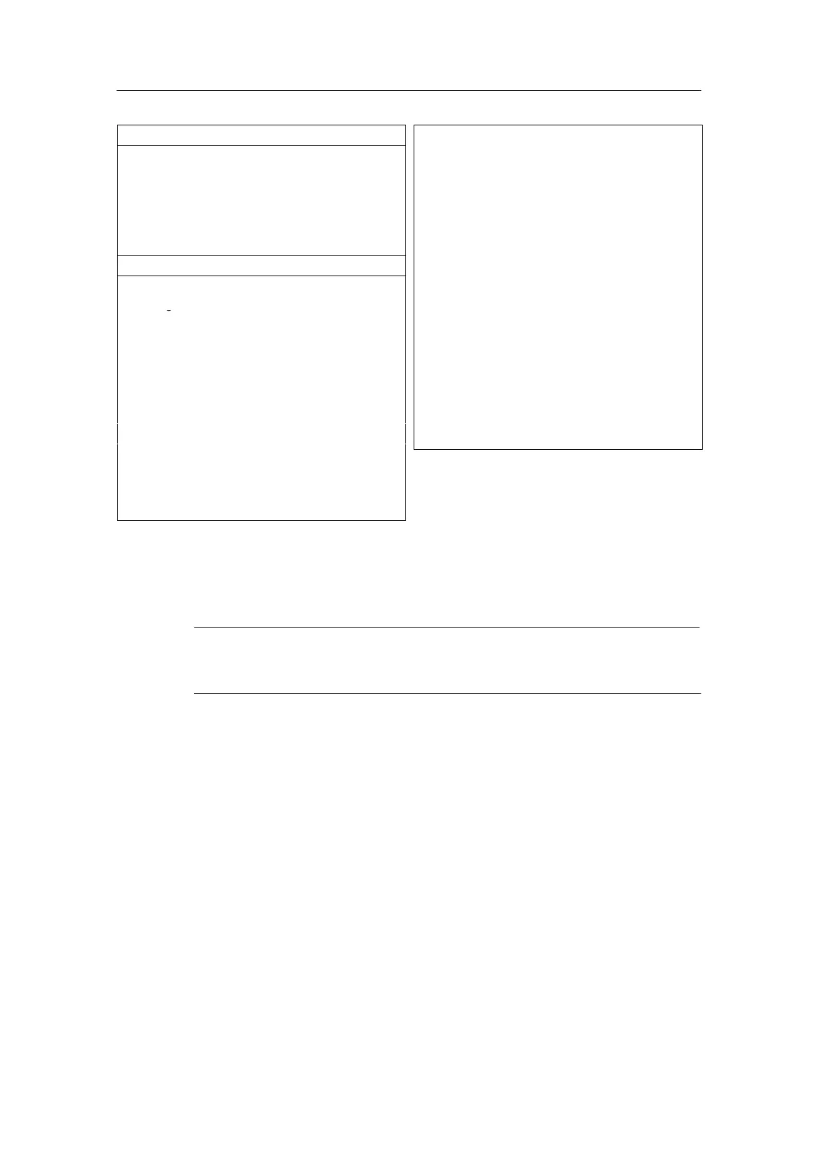
Status, interrupts, diagnostics
Interrupts
• Diagnostic Interrupt
Programmable
Diagnostic functions
• Group error display
• Diagnostics information
read-out
Parameters can be
assigned
Red LED (SF)
Possible
Data for Selecting an Actuator
Output ranges (rated values)
Output ranges (rated values)
Voltage
• Voltage
±
• Current
± 20 mA
0 to 20 mA
4 to 20 mA
Impedance (in the nominal
output range)
• For voltage outputs min. 1 kΩ
– capacitive load max. 1 F
• For current outputs
–At U
CM
< 1 V
– For inductive load
max. 500 Ω
max. 600 Ω
max. 10 mH
Voltage outputs
• Short-circuit protection
• Short-circuit current
Yes
max. 25 mA
Current outputs
• No-load voltage max. 18 V
Destruction limit for
voltages/currents connected
from outside
• Voltage at outputs to M
ANA
max. 18 V continuous;
75 V for max. 1 s
(mark-to-space ratio
1:20)
• Current
max. 50 mA DC
Connection of actuators
• For voltage output
Four-conductor connection
Possible
• For current output
Two-conductor connection
Possible
4.26.1 Commissioning the SM 332; AO 8 x 12 bits
Note
If the load voltage (L+) is switched off and on, this may result in incorrect output
values at the output for approx. 10 ms.
Parameter
You will find a description of the general procedure for assigning parameters to
analog modules in Section 4.7.
You will find an overview of the programmable parameters and their default values
in Table 4-42, on page 4-43.