SIMATIC TOP Connect and SIMATIC TOP Connect TPA
8-18
Programmable Logic Controllers S7-300 Module Data
A5E00105505-03
8.3.4 Wiring the Module with Terminal Block for 2A Modules
You can use the terminal block for 2A modules to wire the SM 322;
8 x DO 24 VDC/2A.
Connection Notes
Table 8-11 Connection Notes for SIMATIC TOP connect with 2A Module Connection
Digital Modules
Connection Notes
Supply Voltage Feed-In Add.
Descr. on
At front
connector
only
Add.
ground
conn. at
terminal
block
At front
connector
or terminal
block
required
for power
supply
block not
in line with
descr. on
SM
SM 322; DO 16 24 VDC/2 A – – –
Assignment of the Terminal Block for Connection of 2A Modules
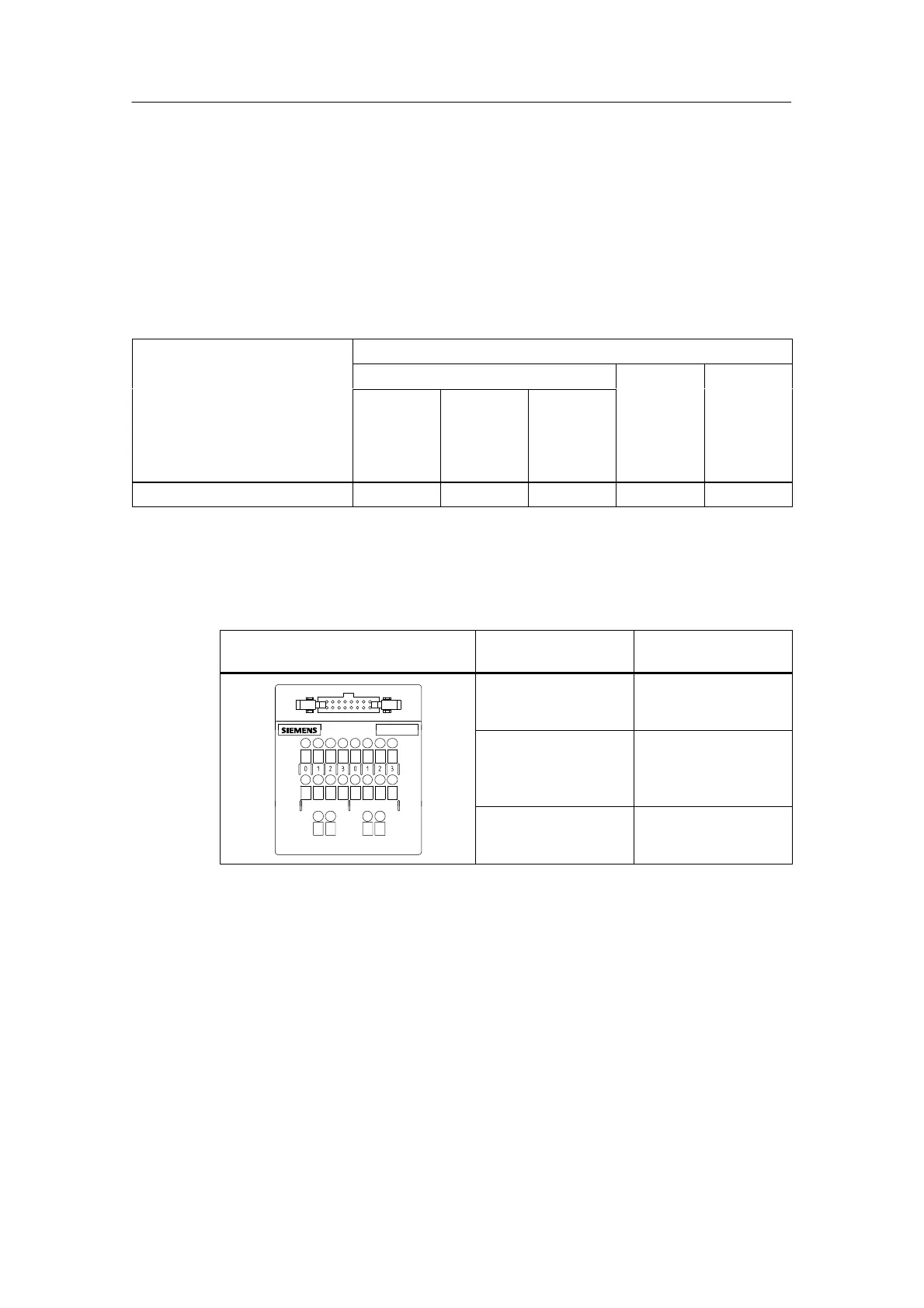
Table 8-12 Terminal Assignments of the Terminal Block for 2A Modules
Front view of terminal block
Assignments of the
Terminals (left)
Assignments of the
Terminals (right)
Top row:
Terminals 0 to 3:
outputs x.0 to x.3
Top row, on right:
Terminals 0 to 3:
outputs x.4 to x.7
Center row:
Terminals 0 to 3:
potential M1 for x.0 to
x.3
Center row, on right:
Terminals 0 to 3:
potential M2 for x.4 to
x.7
M1
M2
Bottom row:
two-terminal
connection for M1
Bottom row:
two-terminal
connection for M2
Connecting the power supply
Please observe the following when connecting the power supply:
• Apply the wiring rules in Table 8-3 on page 8-7.
• Connect the supply voltage at the front connector module to the potential
terminals using separate cables.
• You must equip each terminal block with a cable for M1 or M2, in addition to the
connecting cable.
• Connect M1 or M2 via a separate line with the front connector and the terminal
block. You may jumper the potential of M1 and M2.