Digital Modules
3-107
Programmable Logic Controllers S7-300 Module Data
A5E00105505-03
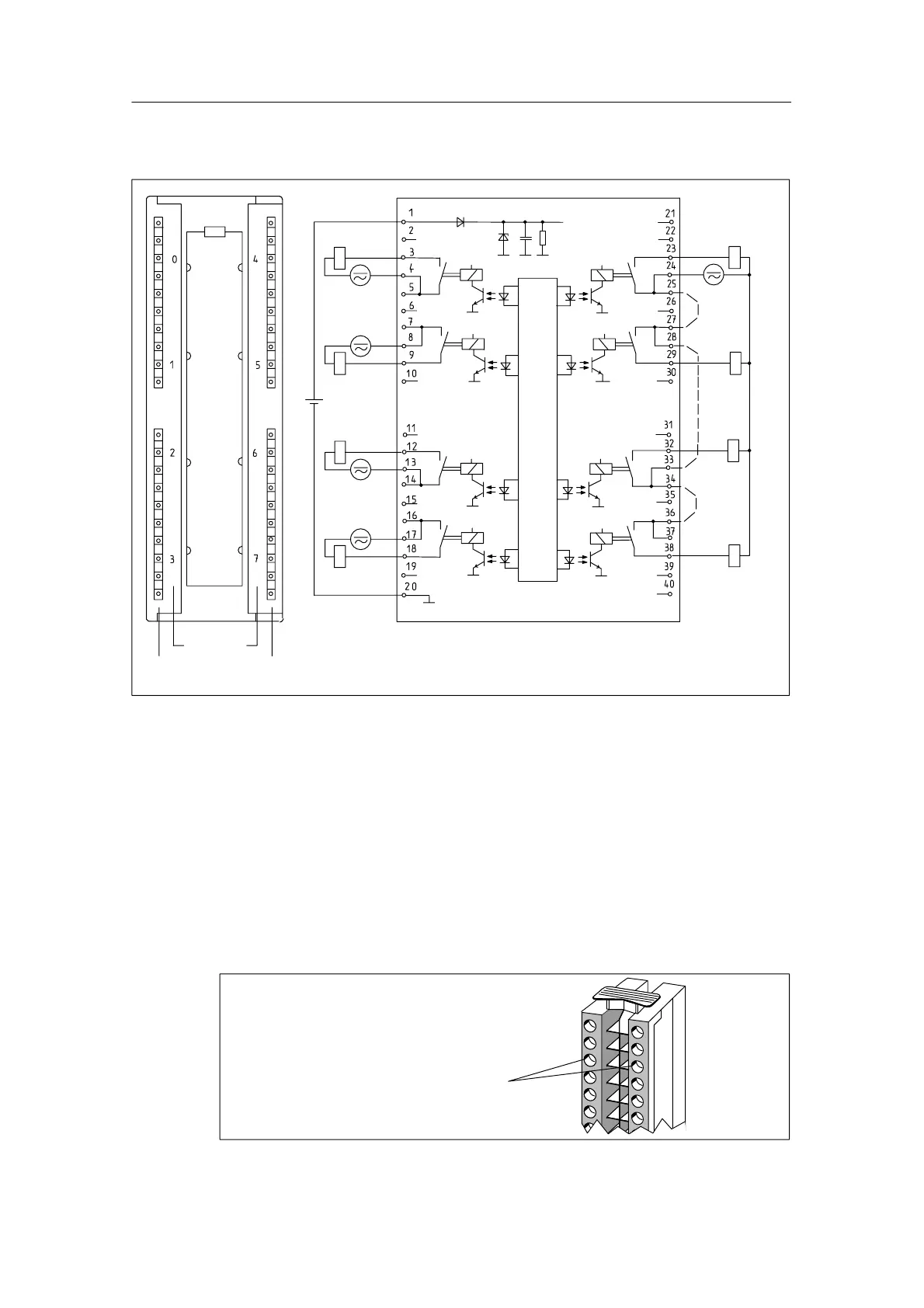
Terminal assignment and block diagram of the SM 322; DO 8 x Rel. 230 VAC/5 A
Channel
number
Status display -green
L+
24 V
M
L+
M
L+
M
L+
M
M
L+
M
L+
M
L+
M
L+
L+
M
M
Backplane bus interface
L+
1)
Connection possibility for contact supply
I
aggregate
current
v8 A for Ta v30 C
I
aggregate
current
v5A for Ta v60 C
1)
1)
1)
Figure 3-34 Module View and Block Diagram of the SM 322; DO 8 x Rel. 230 VAC/5 A
Operation with safe electrical extra-low voltage
When using relay output module 322-1HF10 with safe and electrically isolated
extra-low voltage, take the following special characteristic into account:
If a terminal is operated with a safe and electrically isolated extra-low voltage, the
horizontally adjacent terminal must be operated at a rated voltage of not more
than 120 VUC. With operation at voltages greater than 120 VUC, the creepages
and clearances of the 40-pin front connector do not meet the SIMATIC
requirements for safe electrical isolation.
If one of the two horizontally adjacent termi-
nals is operated with a safe electrical extra-
low voltage, the adjacent terminal must be
operated at not more than UC 120 V.
Figure 3-35 Special Characteristic for Operation with a Safe Electrical Extra-Low Voltage