Analog Modules
4-54
Programmable Logic Controllers S7-300 Module Data
A5E00105505-03
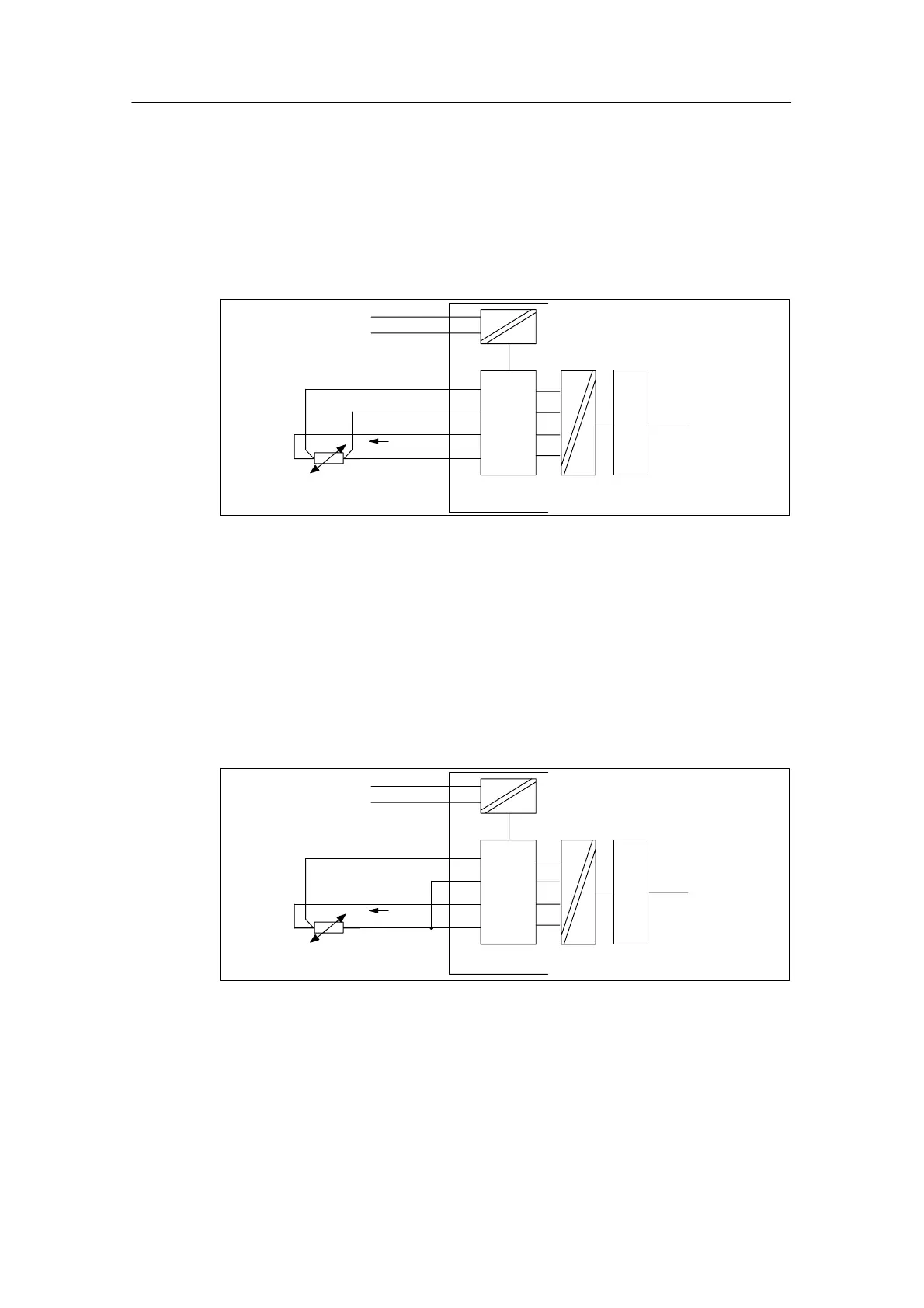
Four-conductor connection of a resistance thermometer
The voltage generated at the resistance thermometer is measured via the M
+
and
M
–
terminals. When you connect, watch out for the polarity of the connected cable
(connect I
C+
and M
+
as well as I
C–
and M– to the resistance thermometer).
When connecting, make sure that the connected cables I
C
+ and M+ and the
cables I
C
– and M– are connected directly to the resistance thermometer.
M+
M
L+
M–
M
ANA
ADC
I
C+
I
C–
I
C
Backplane
bus
Logic
Figure 4-15 Four-conductor connection of resistance thermometers to an isolated AI
Three-conductor connection of a resistance thermometer
With a three-conductor connection on modules with four terminals, you must
normally insert a jumper between M
–
and I
C–
(refer to Figure 4-16). Take note of
the exception for the SM 331; AI 8 RTD (refer to Figure 4-18).
When connecting, make sure that the connected cables I
C
+ and M+ are
connected directly to the resistance thermometer.
M+
M
L+
M–
M
ANA
ADC
I
C+
I
C–
I
C
Backplane
bus
Logic
Figure 4-16 Three-Conductor Connection of Resistance Thermometers to an Isolated AI