Analog Modules
4-136
Programmable Logic Controllers S7-300 Module Data
A5E00105505-03
Unused Channels
Set the “measuring method” parameter for unused channels to “disabled”. In this
way you shorten the scan time of the module.
You must terminate an unused channel of an enabled channel group with a
nominal resistance in order to avoid diagnostic errors for the unused channel (refer
to the block diagram, Figure 4-41, for the connection).
In the “4-Channel Hardware Filter” operating mode, termination is not necessary
provided that you have disabled the unused channel groups. Channels 1, 3, 5 and
7 are not monitored in this mode.
Measuring ranges
You perform setting of the measuring ranges with the “measuring range” parameter
in STEP 7.
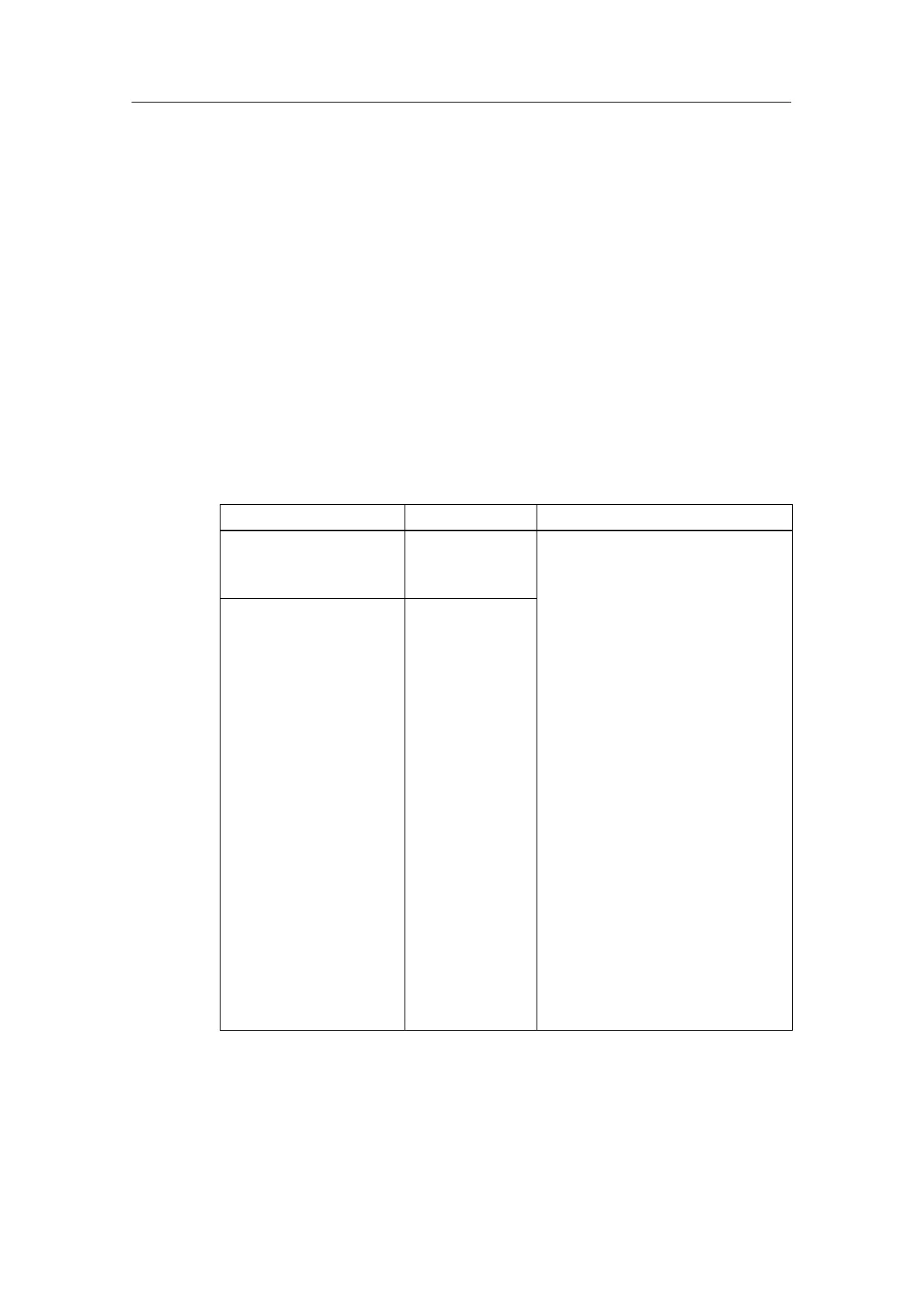
Table 4-71 Measuring ranges of the SM331; AI 8 x RTD
Method Selected
Measuring Range Description
Resistors:
(Three-conductor/four-cond
uctor terminal)
150
300
600
You will find the digital analog values in
Section 4.3.1
Resistance RTD
(Three-conductor/four-cond
uctor terminal)
Pt 100 climate
Pt 200 climate
Pt 500 climate
Pt 1000 climate
Ni 100 climate
Ni 120 climate
Ni 200 climate
Ni 500 climate
Ni 1000 climate
Cu 10 climate
Pt 100 standard
Pt 200 standard
Pt 500 standard
Pt 1000 standard
Ni 100 standard
Ni 120 standard
Ni 200 standard
Ni 500 standard
Ni 1000 standard
Cu 10 standard