EasyManuals Logo

Siemens SIMATIC S7-300 Module data Reference Manual

Siemens SIMATIC S7-300 Module data
574 pages
To Next Page IconTo Next Page
To Previous Page IconTo Previous Page
Page #528 background imageLoading...
Page #528 background image
C-8
Programmable Logic Controllers S7-300 Module Data
A5E00105505-03
Bus modules (Expansion buses)
Figure C-11 shows the dimension drawing of the active bus module for the “Insert
and Remove” function.
Bus modules
BM PS/IM (...7HA)
BM IM/IM (...7HD)
BM 2 40 (...7HB)
BM 1 80 (...7HC)
97
92
Figure C-11 Dimension Drawing of the Active Bus Modules
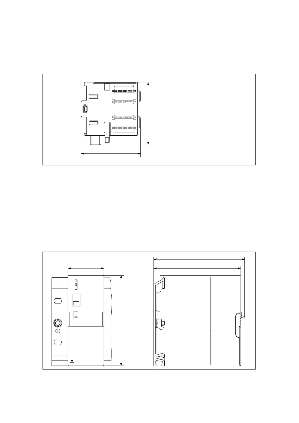
C.2 Dimension Drawings of the Power Supply Modules
PS 307; 2 A
Figure C-12 shows the dimension drawing of the PS 307; 2 A power supply
module.
50 120
127.5
125
Figure C-12 Power Supply Module PS 307; 2 A

Table of Contents

Other manuals for Siemens SIMATIC S7-300 Module data

Questions and Answers:

Question and Answer IconNeed help?

Do you have a question about the Siemens SIMATIC S7-300 Module data and is the answer not in the manual?

Siemens SIMATIC S7-300 Module data Specifications

General IconGeneral
SeriesS7-300
ManufacturerSiemens
Protection ClassIP20
SystemSIMATIC S7-300
Digital InputsVaries by module
Digital OutputsVaries by module
Analog InputsVaries by module
Analog OutputsVaries by module
Central Processing UnitVaries by CPU model
Supply Voltage24V DC or 120/230V AC
CPU TypeVaries (e.g., CPU 312, CPU 315, etc.)
MemoryVaries by CPU model
Communication InterfacesMPI, PROFIBUS
Programming LanguagesLAD, FBD, STL, SCL, GRAPH
Operating Temperature0°C to 60°C
Storage Temperature-40°C to 70°C
Relative Humidity10% to 95% (non-condensing)

Related product manuals