B-2
Programmable Logic Controllers S7-300 Module Data
A5E00105505-03
B.2 Structure and Content of Diagnostic Data Bytes 0 to 7
The structure and contents of the different bytes of the diagnostic data are
described below. The following general rule applies: When an error occurs, the bit
concerned is set to “1”.
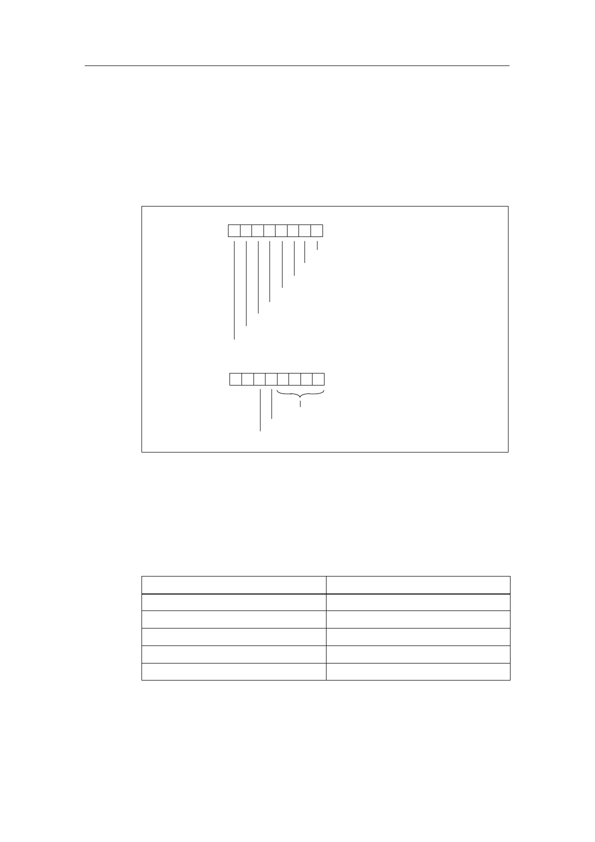
Bytes 0 and 1
Byte 0
76 0
Module problem
Internal malfunction
External malfunction
Channel error present
External auxiliary supply missing
Front connector missing
Module not parameterized.
Incorrect parameter in the module
54321
Byte 1
76 0
Channel information available
User information available
54321
Module type (see Table B-1)
00
Figure B-1 Bytes 0 and 1 of the Diagnostic Data
Module types
The following table contains the IDs of the module classes (bits 0 to 3 in byte 1).
Table B-1 Codes of the Module Types
Code Module Type
0101 Analog module
0110 CPU
1000 Function module
1100 CP
1111 Digital module