SIMATIC TOP Connect and SIMATIC TOP Connect TPA
8-8
Programmable Logic Controllers S7-300 Module Data
A5E00105505-03
Connect the connecting cable and the supply voltage to the front connector
module
1. Open the front door of the module.
2. Bring the front connector into the wiring position.
3. If necessary, connect the cables for the incoming supply of the module supply
voltage.
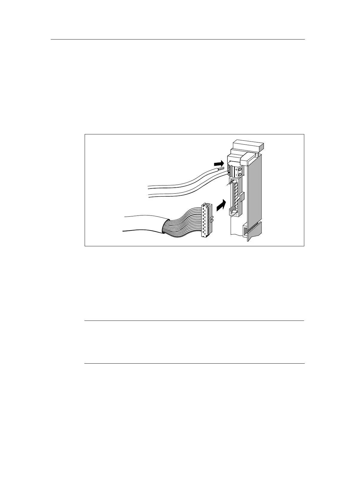
4. Insert the connecting cable into the front connector module as shown in the
following figure:
Figure 8-3 Inserting the Connecting Cable into the Front Connector Module
5. Twist every connecting cable 90 downwards and turn through one whole turn
to the extent possible.
Additional steps for wiring for 32-channel digital modules
Note
When using 32-channel digital modules, you must observe the assignment of the
supply connections to the connecting cable terminals and the assignment of the
connecting cable terminals to the address bytes of the module (refer to Figure 8-4
and Table 8-4).
6. Thread a strain relief assembly into the middle of the front connector. This
strain relief assembly is used to fix the connecting cables in the narrow cable
stowage area of the module.
7. Thread the strain relief assembly into the front connector.