EasyManuals Logo

Siemens SIMATIC S7-300 Module data Reference Manual

Siemens SIMATIC S7-300 Module data
574 pages
To Next Page IconTo Next Page
To Previous Page IconTo Previous Page
Page #459 background imageLoading...
Page #459 background image
SIMATIC TOP Connect and SIMATIC TOP Connect TPA
8-15
Programmable Logic Controllers S7-300 Module Data
A5E00105505-03
Connecting the power supply
Always connect the supply voltage to the front connector module Observe the
wiring rules in Table 8-3 on page 8-7.
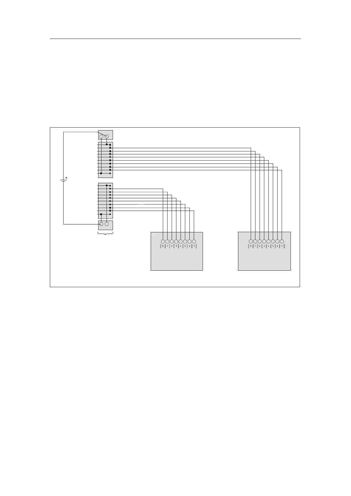
In the following example, you must connect L+ to Plus of the upper terminal and M
to Minus of the lower terminal.
Connecting the terminal block for one-conductor connection
1
2
3
4
5
6
7
8
9
10
Front connector
module
+
11
12
3
1
5
1
6
7
1
8
1
19
20
L+
M
+
Terminal block
Terminal block
Figure 8-8 Wiring a Digital Module with Terminal Block for a One-Conductor Connection
14
1
1

Table of Contents

Other manuals for Siemens SIMATIC S7-300 Module data

Questions and Answers:

Question and Answer IconNeed help?

Do you have a question about the Siemens SIMATIC S7-300 Module data and is the answer not in the manual?

Siemens SIMATIC S7-300 Module data Specifications

General IconGeneral
SeriesS7-300
ManufacturerSiemens
Protection ClassIP20
SystemSIMATIC S7-300
Digital InputsVaries by module
Digital OutputsVaries by module
Analog InputsVaries by module
Analog OutputsVaries by module
Central Processing UnitVaries by CPU model
Supply Voltage24V DC or 120/230V AC
CPU TypeVaries (e.g., CPU 312, CPU 315, etc.)
MemoryVaries by CPU model
Communication InterfacesMPI, PROFIBUS
Programming LanguagesLAD, FBD, STL, SCL, GRAPH
Operating Temperature0°C to 60°C
Storage Temperature-40°C to 70°C
Relative Humidity10% to 95% (non-condensing)

Related product manuals