EasyManuals Logo

Siemens SIMATIC S7-300 Module data Reference Manual

Siemens SIMATIC S7-300 Module data
574 pages
To Next Page IconTo Next Page
To Previous Page IconTo Previous Page
Page #531 background imageLoading...
Page #531 background image
Dimension Drawings
C-11
Programmable Logic Controllers S7-300 Module Data
A5E00105505-03
PS 307; 5 A with CPUs 313/314/315/315-2 DP
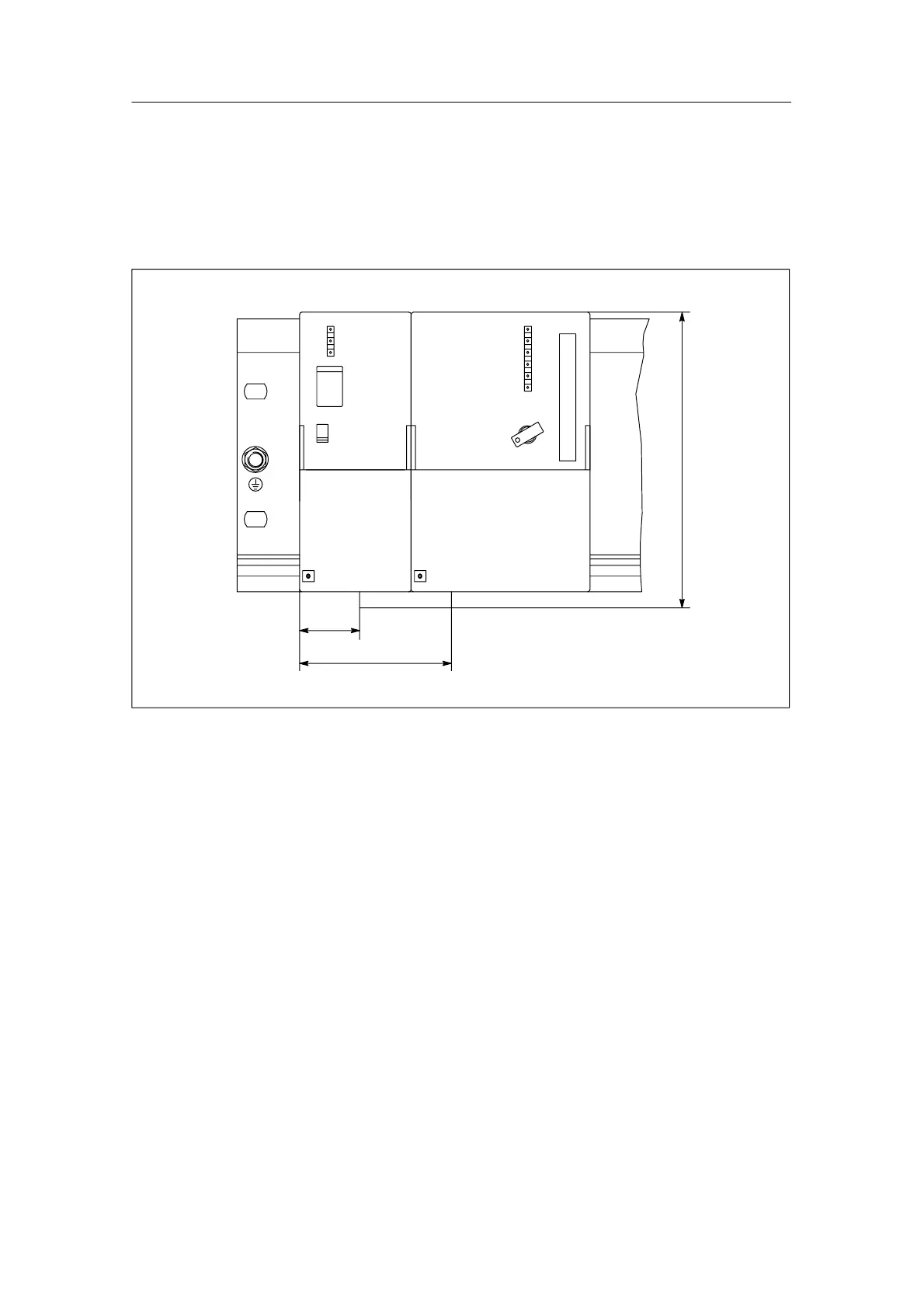
Figures C-15 and C-16 show the dimension drawings of the configuration of a
power supply module PS 307; 5 A with the CPUs 313/314/315/315-2 DP. Observe
the dimensions that result from the use of the power connector for wiring the
PS 307; 5 A with the CPU.
27
68
132
Figure C-15 Dimension Drawing of the Power Supply Module PS 307; 5 A with CPUs
313/314/315/315-2 DP. Front View

Table of Contents

Other manuals for Siemens SIMATIC S7-300 Module data

Questions and Answers:

Question and Answer IconNeed help?

Do you have a question about the Siemens SIMATIC S7-300 Module data and is the answer not in the manual?

Siemens SIMATIC S7-300 Module data Specifications

General IconGeneral
SeriesS7-300
ManufacturerSiemens
Protection ClassIP20
SystemSIMATIC S7-300
Digital InputsVaries by module
Digital OutputsVaries by module
Analog InputsVaries by module
Analog OutputsVaries by module
Central Processing UnitVaries by CPU model
Supply Voltage24V DC or 120/230V AC
CPU TypeVaries (e.g., CPU 312, CPU 315, etc.)
MemoryVaries by CPU model
Communication InterfacesMPI, PROFIBUS
Programming LanguagesLAD, FBD, STL, SCL, GRAPH
Operating Temperature0°C to 60°C
Storage Temperature-40°C to 70°C
Relative Humidity10% to 95% (non-condensing)

Related product manuals