EasyManuals Logo

Siemens SIMATIC S7-300 Module data Reference Manual

Siemens SIMATIC S7-300 Module data
574 pages
To Next Page IconTo Next Page
To Previous Page IconTo Previous Page
Page #158 background imageLoading...
Page #158 background image
Digital Modules
3-74
Programmable Logic Controllers S7-300 Module Data
A5E00105505-03
L+
green
L+ Monitoring
Fuse
Monitoring
Control
red
Group error display (1x)
red
Channel fault LED (8x)
Channel status LED (8x)
M
Output
(8x)
SF
Diagnostics
Status
F ƪ0 to 7ƫ
ƪ0 to 7ƫ
Output
drivers
(8 x)
Output
Backplane
bus
Logic
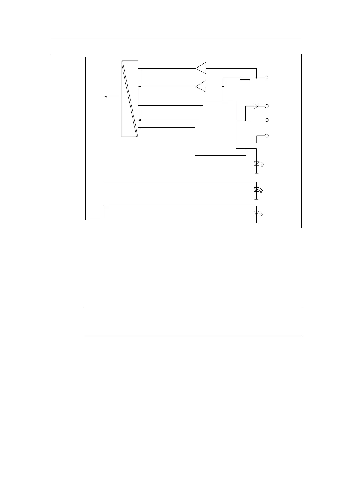
Figure 3-26 Block Diagram of the SM 322; DO 8 DC 24 V/0.5 A
Redundant control of a load
The output with series diode can be used for redundant control of a load.
Redundant control is possible from two different signal modules without external
circuitry. Both modules must have the same reference potential, M.
Note
If the output with series diode is used, external short-circuits to L+ cannot be
detected.

Table of Contents

Other manuals for Siemens SIMATIC S7-300 Module data

Questions and Answers:

Question and Answer IconNeed help?

Do you have a question about the Siemens SIMATIC S7-300 Module data and is the answer not in the manual?

Siemens SIMATIC S7-300 Module data Specifications

General IconGeneral
SeriesS7-300
ManufacturerSiemens
Protection ClassIP20
SystemSIMATIC S7-300
Digital InputsVaries by module
Digital OutputsVaries by module
Analog InputsVaries by module
Analog OutputsVaries by module
Central Processing UnitVaries by CPU model
Supply Voltage24V DC or 120/230V AC
CPU TypeVaries (e.g., CPU 312, CPU 315, etc.)
MemoryVaries by CPU model
Communication InterfacesMPI, PROFIBUS
Programming LanguagesLAD, FBD, STL, SCL, GRAPH
Operating Temperature0°C to 60°C
Storage Temperature-40°C to 70°C
Relative Humidity10% to 95% (non-condensing)

Related product manuals