SIMATIC TOP Connect and SIMATIC TOP Connect TPA
8-24
Programmable Logic Controllers S7-300 Module Data
A5E00105505-03
8.4.4 Connection Example
Connecting the load voltage supply
You can connect the load voltage supply of the analog module to the front
connector module. There are separate terminals on the front connector module for
the load voltage L+ and M. Observe the wiring rules in Table 8-3 on page 8-7.
Allocation of front connector to terminal block
The upper socket of the front connector module is the connection for terminal
block 1 and the lower socket of the front connector module is the connection for
terminal block 2.
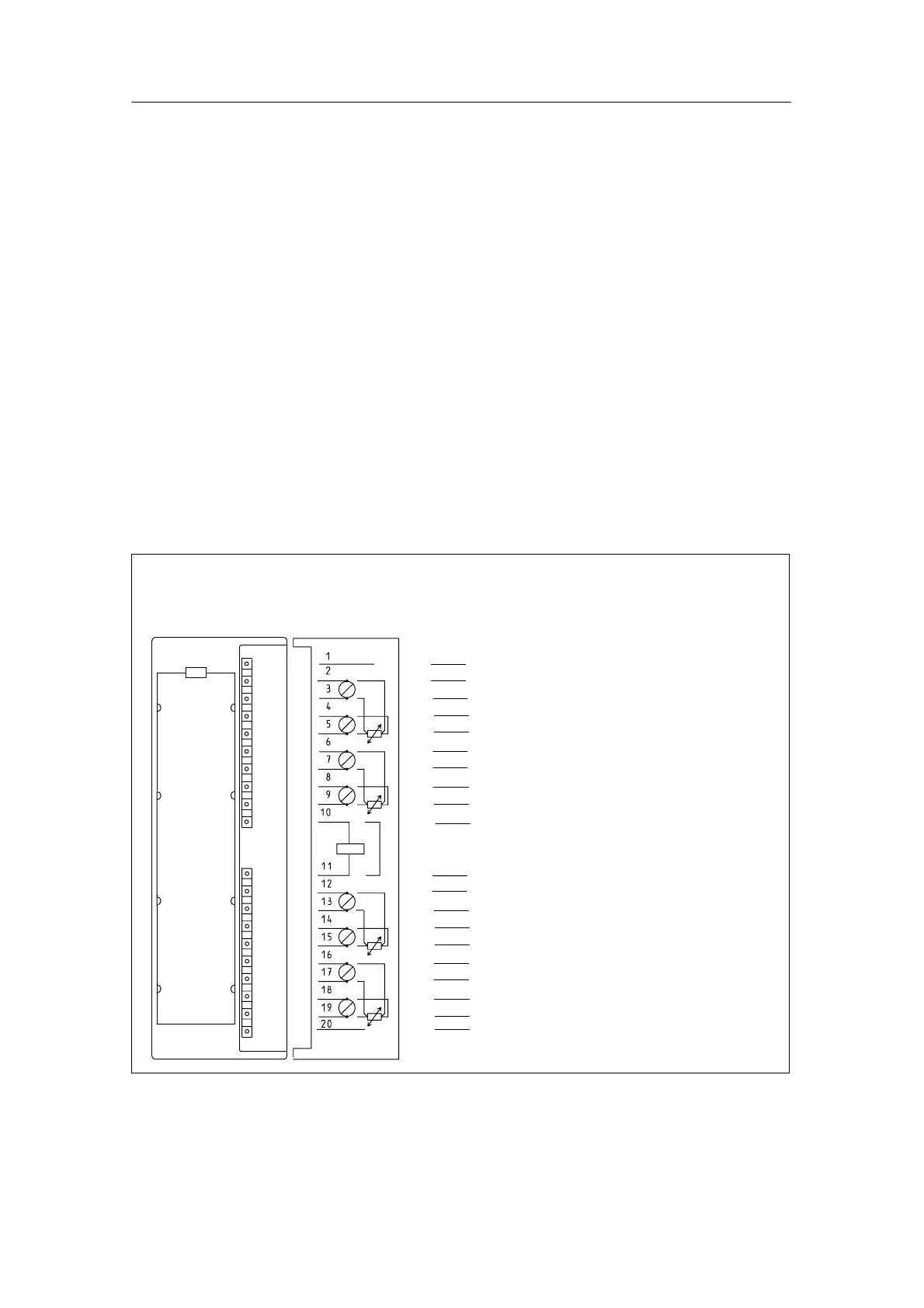
Connection example
The illustration below shows an example of connecting the analog input module
SM 321; AI 8 x 12 bits in “Resistance Test” mode.
Comp–/ Mana
Resistance
test
Comp +
SF
M
L+
M
0
+
CH0
M
0
*
I
C0
+
I
C0
*
M
1
+
CH2
M
1
*
I
C1
+
I
C1
*
M
2
+ CH4
M
2
*
I
C2
+
I
C2
*
M
3
+
CH6
M
3
*
I
C3
+
I
C3
*
Comp
M
L
+
M
Terminal assignment
on terminal block TPA
Terminal
block 1
Terminal
block 2
12
11
13
14
15
16
17
18
19
20
Y
B
C
D
E
F
G
H
I
K
A
Z
Y
K
B
A
C
D
E
F
G
H
I
Z
2
1
3
4
5
6
7
8
9
10
Terminal number
on module
Figure 8-13 Example of Connecting SIMATIC TOP connect TPA to SM 321; AI 8 x 12 bits

 Loading...


