Analog Modules
4-189
Programmable Logic Controllers S7-300 Module Data
A5E00105505-03
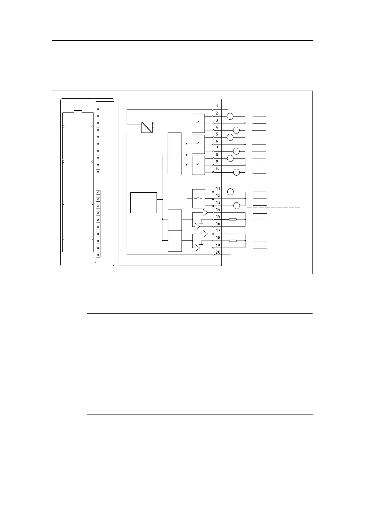
Module View and Block Diagram of the SM 334; AI 4/AO 2 x 8/8 bits
Select the measuring method of the input channels and the output type of the
output channels via the wiring.
Internal
supply
Backplane
bus
interface
L +
24V
DAC
M
M
MV
0 +
M
0
*
MV
1 +
MI
0 +
M
1
*
MI
1 +
MV
2 +
M
2
*
MI
2 +
MV
3 +
M
3
*
MI
3 +
CH0
CH1
CH2
CH3
QV
0
M
ANA
QI
0
QV
1
M
ANA
QI
1
CH0
CH1
ADC
Voltage
Current outputs
Voltage
Current measurement
M
ANA
M
ANA
V
A
V
A
A
V
A
V
A
V
V
A
Figure 4-55 Module View and Block Diagram of the Analog Input/Output Module SM 334;
AI 4/AO 2 x 8/8 bits
Note
Note when connecting the SM 334 that:
• the analog chassis ground M
ANA
(terminal 15 or 18) is connected to the
chassis ground M of the CPU and/or the interface module (IM). Use a wire
with a minimum cross-section of 1 mm
2
for this.
If there is no ground connection between M
ANA
and M, the module switches
off. Inputs are read with 7FFF
H
; outputs return a value of 0. If the module is run
without a ground connection for some time, it may be destroyed.
• The supply voltage for the CPU and/or the interface module (IM) must not
be connected with reversed polarity. Reverse polarity causes the
destruction of the module because M
ANA
is subjected to an unauthorized high
potential (+24 V).

 Loading...


