Analog Modules
4-76
Programmable Logic Controllers S7-300 Module Data
A5E00105505-03
Note
Note that a hardware interrupt is not triggered if you have set the upper limit above
the overrange or the lower limit below the underrange.
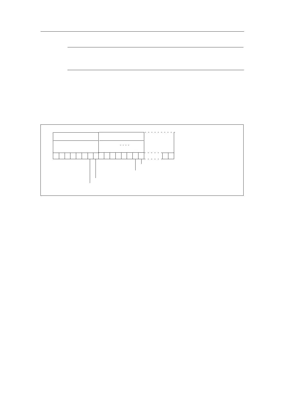
Structure of the start information tag OB40_POINT_ADDR of OB 40
The limit values exceeded by the different channels are entered in the start
information of OB 40 in the tag OB40_POINT_ADDR. The following figure shows
the assignment to the bits of local data double word 8.
1
16
Bit no.
17
3130
29 28 27 26
LD 81
LB 8
LB 9
25 24
Value exceeds upper limit in channel 0
Value falls below lower limit in channel 0
Value exceeds upper limit in channel 1
LB 11
0
1
Value falls below lower limit in channel 1
11
.0
.1
Figure 4-32 Start Information of OB 40: Which Event Has Triggered the Hardware Interrupt at the
Limit Value
Hardware interrupt upon trigger “Reached end of scan cycle”
By parameterizing the hardware interrupt a the end of the scan cycle, you have the
option of synchronizing a process with the scan cycle of the analog input module.
A scan cycle includes the conversion of the measured values of all enabled
channels of the analog input module. The module processes the channels one
after the other. After all the measured values have been converted, the module of
the CPU reports by means of an interrupt that there are new measured values on
all channels.
You can use the interrupt to load the currently converted analog values.