Analog Modules
4-83
Programmable Logic Controllers S7-300 Module Data
A5E00105505-03
4.18.2 Measuring Methods and Measuring Ranges of the SM 331;
AI 8 x 16 bits
Measuring Methods
You can set the following measuring methods for the input channels:
• Voltage measurement
• Current measurement
You perform the setting with the “measuring method” parameter in STEP 7.
Unused Channels
Set the “measuring method” parameter for unused channels to “disabled”. In this
way you shorten the scan time of the module.
Since configured inputs can remain unused because of the channel group
generation, you must take note of the following special characteristics of these
inputs to enable the diagnostic functions on the used channels.
• Measuring range 1 to 5 V: Connect the unused input in parallel with a used
input of the same channel group.
• Current measurement 4 to 20 mA: Connect the unused input in series with an
input of the same channel group. Ensure that a current sense resistor is
connected for each active and unused channel.
• Other ranges: Short the positive to the negative input of the channel.
Measuring ranges
The measuring ranges are set with the “measuring range” parameter in STEP 7.
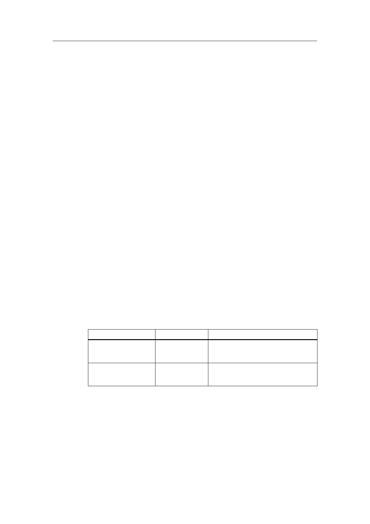
Table 4-52 Measuring Ranges of the SM 331; AI 8 x 16 bits
Method Selected
Measuring Range Description
U: Voltage ±5 V
1 to 5 V
±10 V
You will find the digitized analog values in
Section 4.3.1 in the voltage measuring
range
4DMU: Current (4-wire
transmitter)
from 0 to 20 mA
±20 mA
from 4 to 20 mA
You will find the digitized analog values in
Section 4.3.1 in the current measuring
range

 Loading...


