SIMATIC TOP Connect and SIMATIC TOP Connect TPA
8-10
Programmable Logic Controllers S7-300 Module Data
A5E00105505-03
8.2.3 Connecting the Connecting Cable to the Terminal Block
Introduction
A description of how to mount the terminal blocks is presented in the following.
Note also the special sections for SIMATIC TOP connect and SIMATIC TOP
connect TPA (Section 8.3 and 8.4, respectively). In those sections, you will find,
among other things, selection criteria for the different terminal blocks and specific
connection examples.
Mounting the terminal block and connecting cable
1. Attach the terminal block to a 35 mm standard rail in accordance with
EN 50 022.
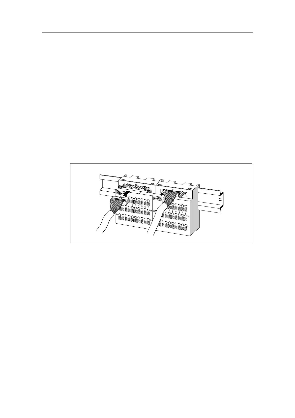
2. Insert the connecting cable into the terminal block as shown in the following
figure:
Figure 8-5 Insert the connecting cable into the terminal block
8.2.4 Wiring Actuators/Sensors to the Terminal Block
Screw-type or spring-loaded terminals
To mount the signal leads of the actuators/sensors to the terminal block and the
supply lines to the terminal block and front connector module, you can choose
between screw-type and spring-loaded components.
The principle of spring-loaded components is dealt with in greater detail in the
following, since it allows fast and simple connection of the signal lines and supply
cables.

 Loading...


