Analog Modules
4-55
Programmable Logic Controllers S7-300 Module Data
A5E00105505-03
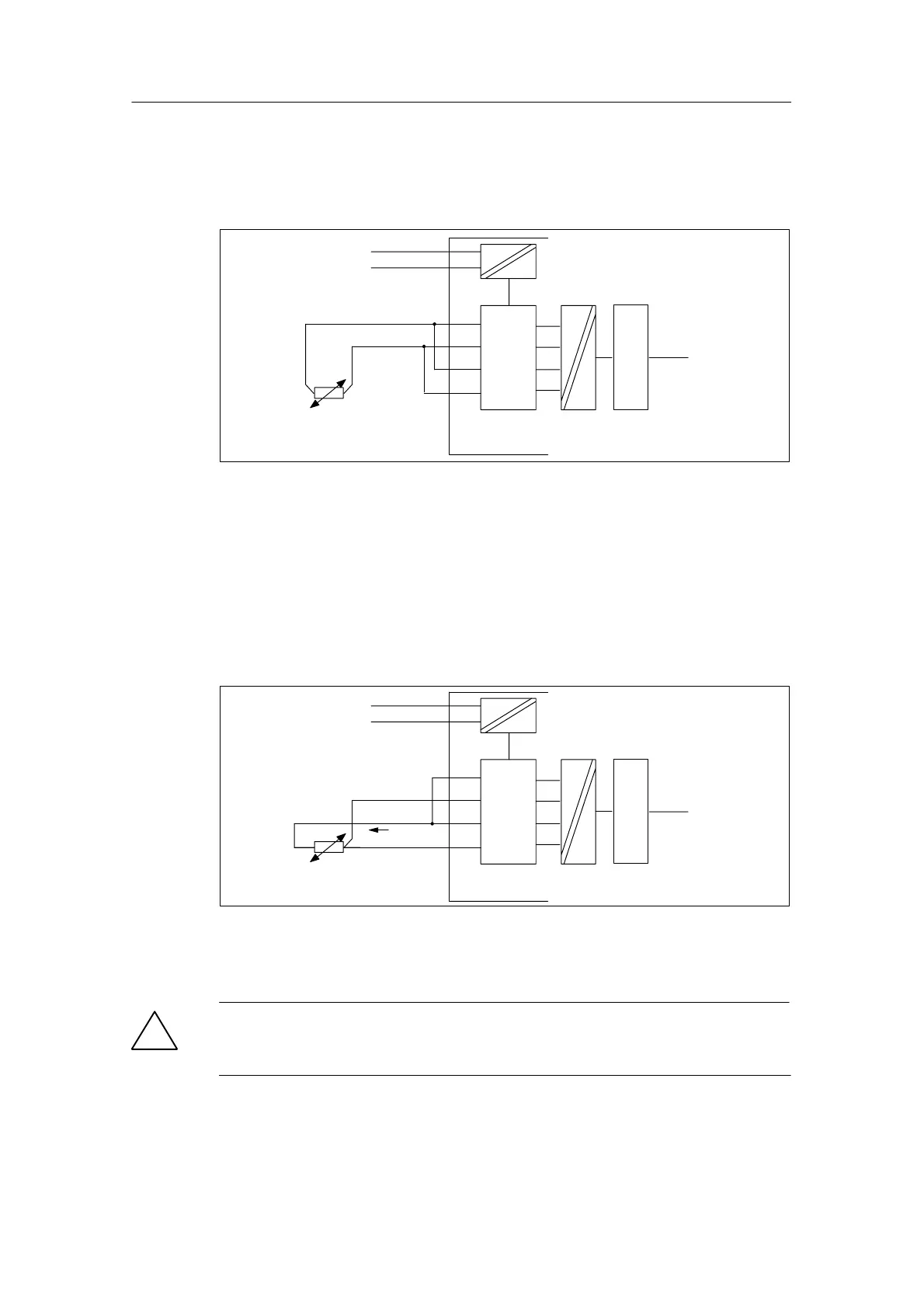
Two-conductor connection of a resistance thermometer
With a two-conductor connection, you must insert jumpers on the module between
M
+
and I
C+
and between M
–
and I
C–
.
M+
M
L+
M–
M
ANA
ADC
I
C+
I
C–
Backplane
bus
Logic
Figure 4-17 Two-Conductor Connection of Resistance Thermometers to an Isolated AI
Three-conductor connection to the SM 331; AI 8 RTD
With a three-conductor connection to the SM 331; AI 8 RTD you must insert a
jumper between M
+
and I
C+
(refer to figure4-18).
When connecting, make sure that the connected cables I
C
– and M– are connected
directly to the resistance thermometer.
M+
M
L+
M–
M
ANA
ADC
I
C+
I
C–
I
C
Backplane
bus
Logic
Figure 4-18 Three-Conductor Connection of Resistance Thermometers to the SM 331;
AI 8 x RTD
!
Caution
Due to incorrect wiring of the three-conductor connection, unforeseen operation of
the module and dangerous conditions can result in the system.