EasyManuals Logo

Siemens SIMATIC S7-300 Module data Reference Manual

Siemens SIMATIC S7-300 Module data
574 pages
To Next Page IconTo Next Page
To Previous Page IconTo Previous Page
Page #262 background imageLoading...
Page #262 background image
Analog Modules
4-56
Programmable Logic Controllers S7-300 Module Data
A5E00105505-03
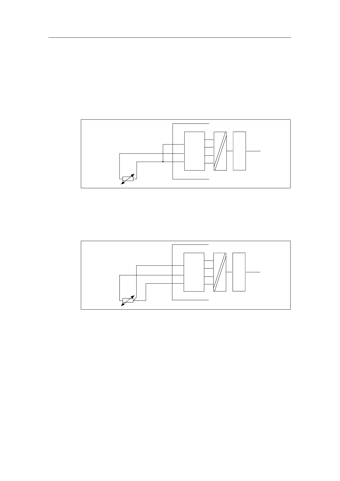
4.11.1 Connecting resistance thermometers to the SM 331;
AI 8 x 13 bits
Two-conductor connection
With a two-conductor connection, you must insert jumpers on the module between
M–
and S–.
Backplane
bus
M+
M–
ADC
S–
Logic
Figure 4-19 Two-conductor connection of resistance thermometers to the SM 331;
AI 8x 13 bits
Three-conductor connection
M+
M–
ADC
S–
Backplane
bus
Logic
Figure 4-20 Three-conductor connection of resistance thermometers to the SM 331;
AI 8 x 13 bits

Table of Contents

Other manuals for Siemens SIMATIC S7-300 Module data

Questions and Answers:

Question and Answer IconNeed help?

Do you have a question about the Siemens SIMATIC S7-300 Module data and is the answer not in the manual?

Siemens SIMATIC S7-300 Module data Specifications

General IconGeneral
SeriesS7-300
ManufacturerSiemens
Protection ClassIP20
SystemSIMATIC S7-300
Digital InputsVaries by module
Digital OutputsVaries by module
Analog InputsVaries by module
Analog OutputsVaries by module
Central Processing UnitVaries by CPU model
Supply Voltage24V DC or 120/230V AC
CPU TypeVaries (e.g., CPU 312, CPU 315, etc.)
MemoryVaries by CPU model
Communication InterfacesMPI, PROFIBUS
Programming LanguagesLAD, FBD, STL, SCL, GRAPH
Operating Temperature0°C to 60°C
Storage Temperature-40°C to 70°C
Relative Humidity10% to 95% (non-condensing)

Related product manuals