Analog Modules
4-48
Programmable Logic Controllers S7-300 Module Data
A5E00105505-03
Non-isolated sensors
The non-isolated sensors are connected with the local ground potential (local
ground). When using non-isolated sensors, you must connect M
ANA
to the local
ground.
Connecting non-isolated sensors
Caused by local conditions or interferences, potential differences U
CM
(static or
dynamic) can occur between the locally distributed individual measuring points. If
the potential difference U
CM
exceeds the permissible value, you must provide
equipotential bonding conductors between the measuring points.
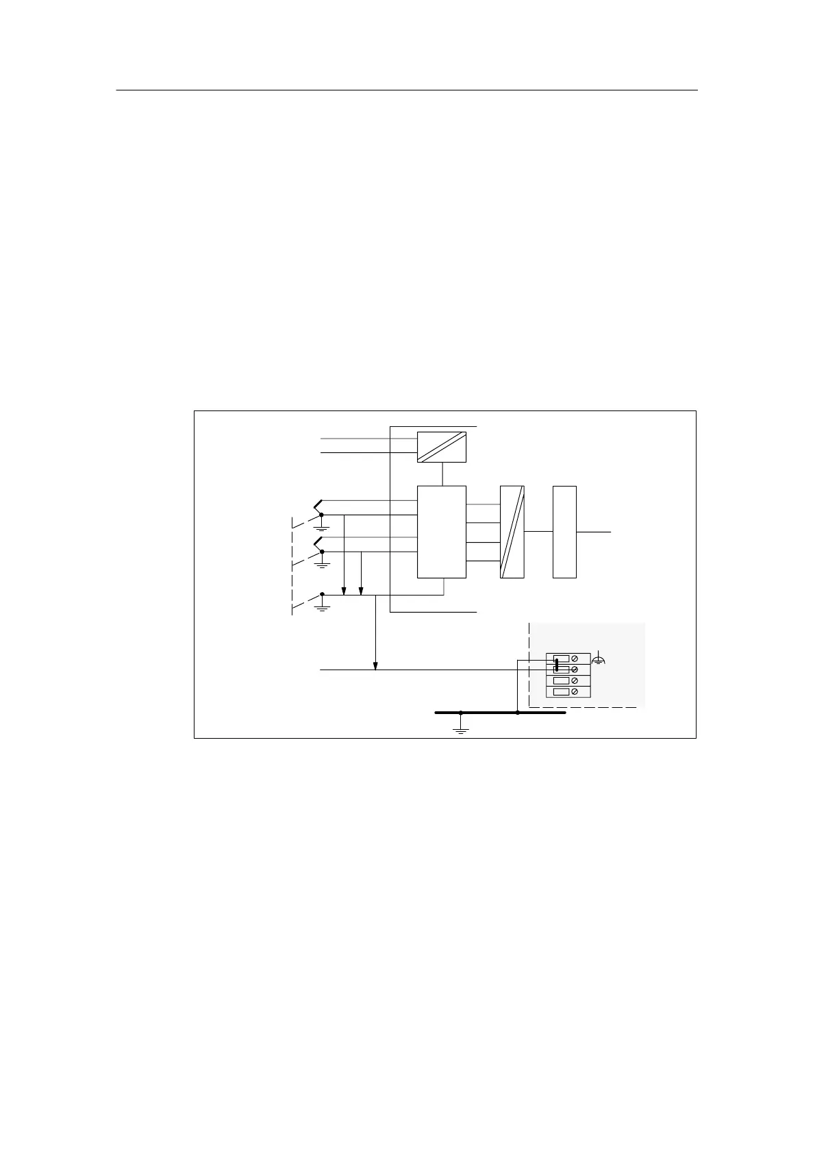
When connecting non-isolated sensors to optically isolated modules, you can
operate the CPU in Grounded mode (refer to the figure below) or Ungrounded
mode.
Non-isolat
ed sensors
M+
M
L+
M–
M
ANA
M+
M–
Backplane bus
U
CM
ADC
M
interna
l
L+
M
Ground bus
CPU
U
ISO
Equipotential
bonding
conductor
Logic
Figure 4-9 Connecting Non-Isolated Sensors to an Isolated AI

 Loading...


