EasyManuals Logo

Siemens SIMATIC S7-300 Module data Reference Manual

Siemens SIMATIC S7-300 Module data
574 pages
To Next Page IconTo Next Page
To Previous Page IconTo Previous Page
Page #275 background imageLoading...
Page #275 background image
Analog Modules
4-69
Programmable Logic Controllers S7-300 Module Data
A5E00105505-03
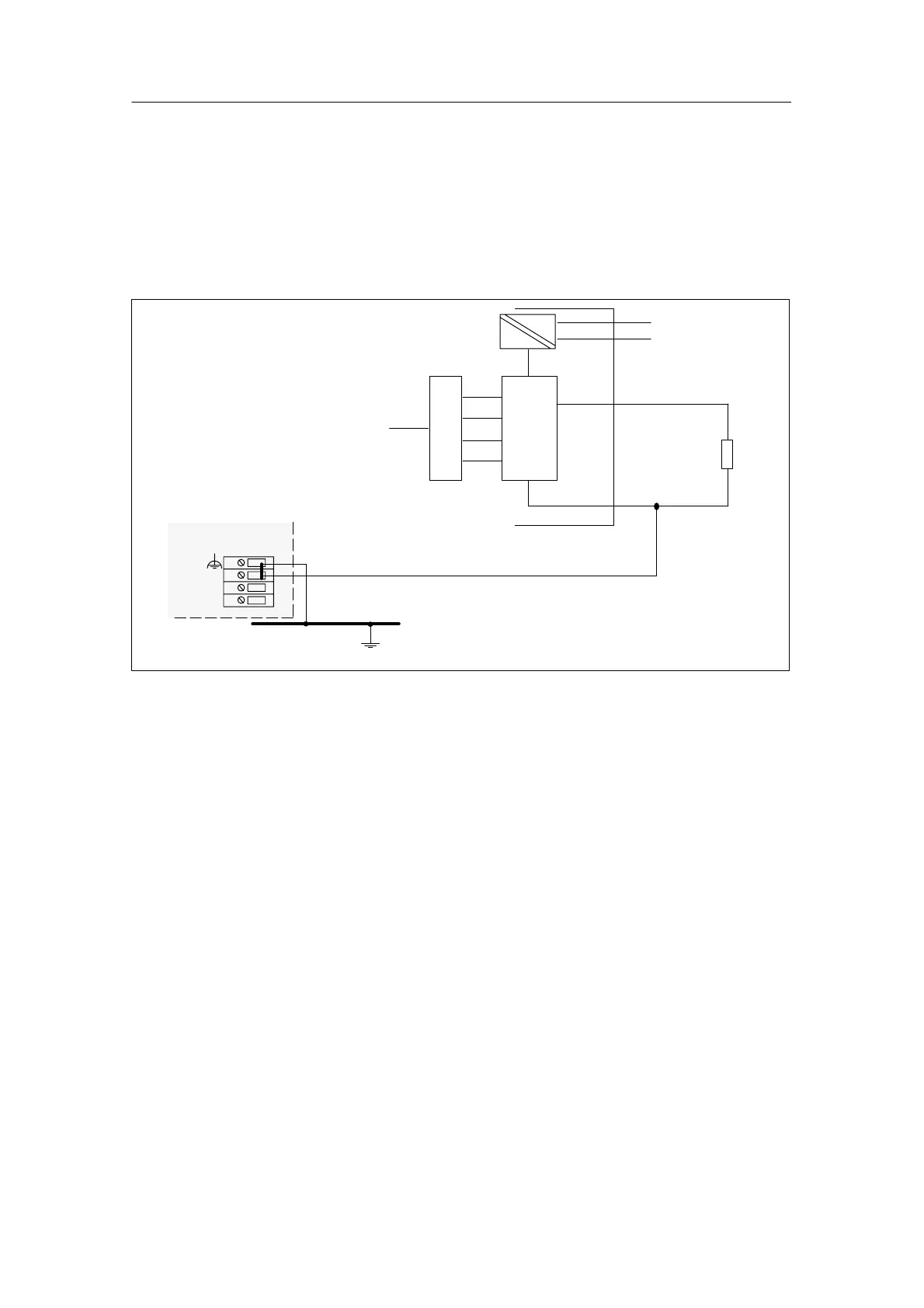
Connecting loads to a voltage output of a non-isolated module via a
two-conductor connection
With a two-conductor connection, the S+ and S– terminals can be left open.
However, you will not achieve the accuracy of a four-conductor connection.
Connect the load to terminals Q
V
and the reference point of the measuring circuit,
M
ANA
.
M
L+
Backplane
bus
DAC
M
internal
L+
M
Ground bus
CPU
R
L
Q
V
M
ANA
Logic
Figure 4-29 Connecting Loads to a Voltage Output of a Non-Isolated AO over a Two-Conductor
Connection

Table of Contents

Other manuals for Siemens SIMATIC S7-300 Module data

Questions and Answers:

Question and Answer IconNeed help?

Do you have a question about the Siemens SIMATIC S7-300 Module data and is the answer not in the manual?

Siemens SIMATIC S7-300 Module data Specifications

General IconGeneral
SeriesS7-300
ManufacturerSiemens
Protection ClassIP20
SystemSIMATIC S7-300
Digital InputsVaries by module
Digital OutputsVaries by module
Analog InputsVaries by module
Analog OutputsVaries by module
Central Processing UnitVaries by CPU model
Supply Voltage24V DC or 120/230V AC
CPU TypeVaries (e.g., CPU 312, CPU 315, etc.)
MemoryVaries by CPU model
Communication InterfacesMPI, PROFIBUS
Programming LanguagesLAD, FBD, STL, SCL, GRAPH
Operating Temperature0°C to 60°C
Storage Temperature-40°C to 70°C
Relative Humidity10% to 95% (non-condensing)

Related product manuals