Digital Modules
3-11
Programmable Logic Controllers S7-300 Module Data
A5E00105505-03
3.3 Digital Module Parameter Assignment
Introduction
Digital modules can have different characteristics. You can set the characteristics
of dome modules by means of parameter assignment.
The information contained in this section refers only to the programmable digital
modules:
• Digital input module SM 321; DI 16 x DC 24 V with process and diagnosis
alarm, synchronous; (6ES7321-7BH01-0AB0)
• Digital input module SM 322; DO 8 x VDC 24/0.5 A with diagnostic interrupt
(6ES7322-8BF00-0AB0)
• Digital output module SM 322; DO 8 x 120/230 VAC /2A ISOL
(6ES7322-5FF00-0AB0)
• Relay output module SM 322; DO 8 x Rel. 230 VAC /5A
(6ES7322-5HF00-0AB0)
• Digital Input/Output Module SM 327; DI 8/DX 8 x VDC 24/0.5 A
(6ES7327-1BH00-0AB0)
Tools for parameter assignment
You assign parameters to digital modules in STEP 7. You must perform parameter
assignment in STOP mode of the CPU.
When you have set all the parameters, download the parameters from the
programming device to the CPU. On a transition from STOP ³ to RUN mode, the
CPU then transfers the parameters to the individual digital modules.
Static and dynamic parameters
The parameters are divided into static and dynamic parameters.
Set the static parameters in STOP mode of the CPU, as described above.
You can also change the dynamic parameters in the running user program in an S7
logic control using SFC. Note, however, that after a change from RUN ³ STOP,
STOP ³ RUN of the CPU, the parameters set in STEP 7 apply again. You will find
a description of the parameter assignment of modules in the user program in
Appendix A.
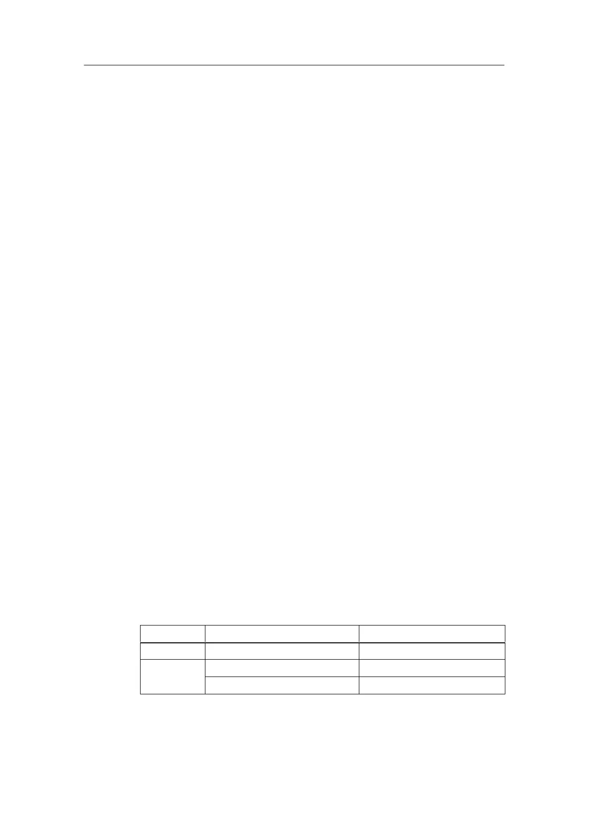
Parameter Settable with CPU Operating State
Static PG (STEP 7 HW CONFIG) STOP
Dynamic PG (STEP 7 HW CONFIG) STOP
SFC 55 in the user program RUN