EasyManuals Logo

Siemens SIMATIC S7-300 Module data Reference Manual

Siemens SIMATIC S7-300 Module data
574 pages
To Next Page IconTo Next Page
To Previous Page IconTo Previous Page
Page #236 background imageLoading...
Page #236 background image
Analog Modules
4-30
Programmable Logic Controllers S7-300 Module Data
A5E00105505-03
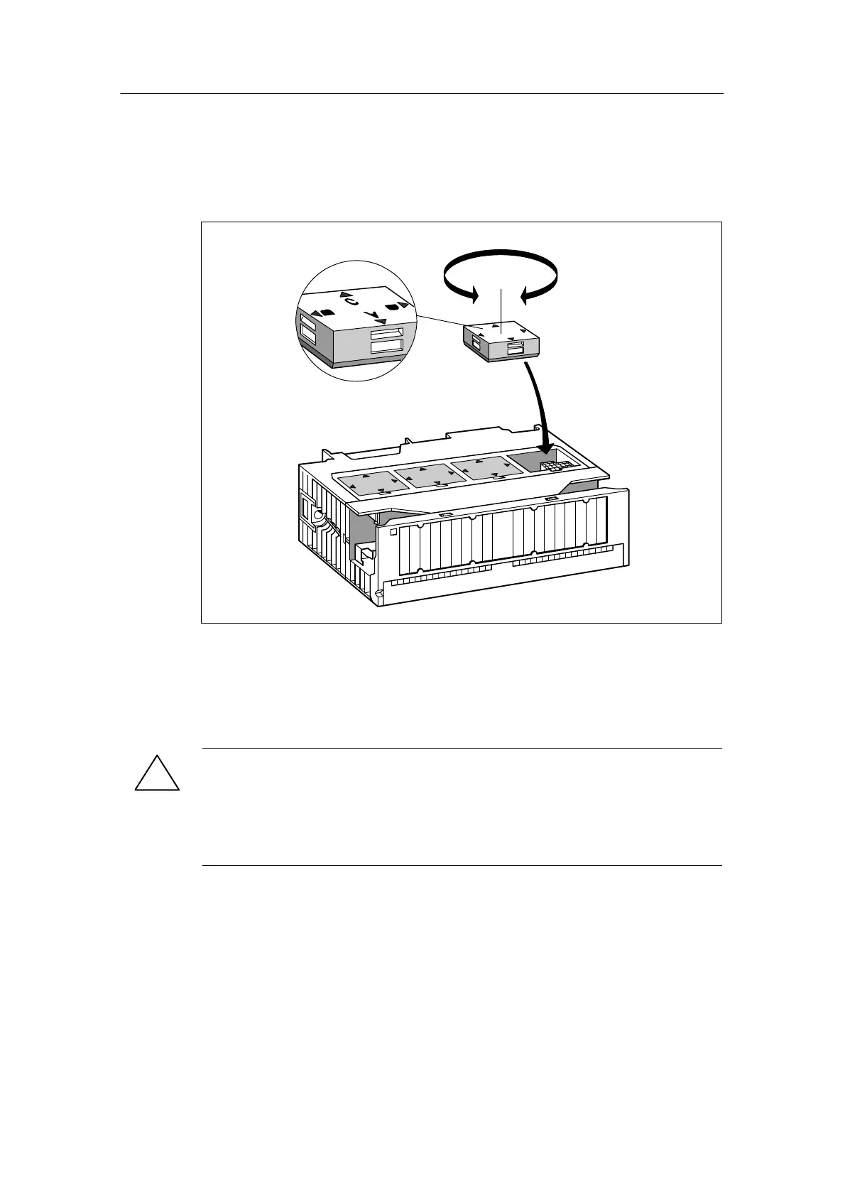
2. Insert the measuring range module (correctly positioned (1)) into the analog
input module.
The measuring range selected is the one that points to marker point on
module (2).
1
2
Figure 4-2 Inserting Measuring Range Modules into the Analog Input Module
Perform the same steps for all other measuring range modules.
The next step is to install the module.
!
Caution
If you have not set the measuring range modules correctly, the module may be
destroyed.
Make sure that the measuring range module is in the correct position before
connecting a sensor to the module.

Table of Contents

Other manuals for Siemens SIMATIC S7-300 Module data

Questions and Answers:

Question and Answer IconNeed help?

Do you have a question about the Siemens SIMATIC S7-300 Module data and is the answer not in the manual?

Siemens SIMATIC S7-300 Module data Specifications

General IconGeneral
SeriesS7-300
ManufacturerSiemens
Protection ClassIP20
SystemSIMATIC S7-300
Digital InputsVaries by module
Digital OutputsVaries by module
Analog InputsVaries by module
Analog OutputsVaries by module
Central Processing UnitVaries by CPU model
Supply Voltage24V DC or 120/230V AC
CPU TypeVaries (e.g., CPU 312, CPU 315, etc.)
MemoryVaries by CPU model
Communication InterfacesMPI, PROFIBUS
Programming LanguagesLAD, FBD, STL, SCL, GRAPH
Operating Temperature0°C to 60°C
Storage Temperature-40°C to 70°C
Relative Humidity10% to 95% (non-condensing)

Related product manuals