Analog Modules
4-32
Programmable Logic Controllers S7-300 Module Data
A5E00105505-03
Behavior on failure of the supply voltage
Failure of the supply voltage of the analog modules is always indicated by the SF
LED on the module. Furthermore, this information is made available on the module
(entry in diagnostic buffer).
Triggering of the diagnostic interrupt depends on the parameter assignment (see
Section 4.7).
4.5.2 Effect of Range of Values of the Analog Values
Effect of errors on analog modules with diagnostics capability
Any errors that occur can lead to a diagnostics entry and a diagnostic interrupt with
analog modules with diagnostics capability and corresponding parameter
assignment. You will find the errors that might be involved in Section 4.16.
Effect of range of values on the analog input module
The behavior of the analog modules depends on where the input values lie within
the range of values.
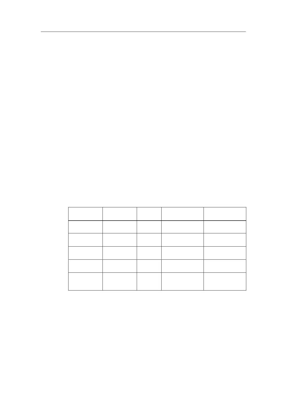
Table 4-39 Behavior of the Analog Input Modules as a Function of the Position of the
Analog Value within the Range of Values
Measured
Value In
Input Value SF LED Diagnostics Interrupt
Rated range Measured
value
– – –
Overrange/und
errange
Measured
value
– – –
Overflow 7FFF
H
Flashes
1)
Entered
1)
Diagnostic
interrupt
1)
Underflow 8000
H
Flashes
1)
Entered
1)
Diagnostic
interrupt
1)
Beyond the
programmed
limit
Measured
value
– – Hardware
interrupt
1)
1)
Only for modules with diagnostics capability and depending on parameter assignment

 Loading...


