Analog Modules
4-78
Programmable Logic Controllers S7-300 Module Data
A5E00105505-03
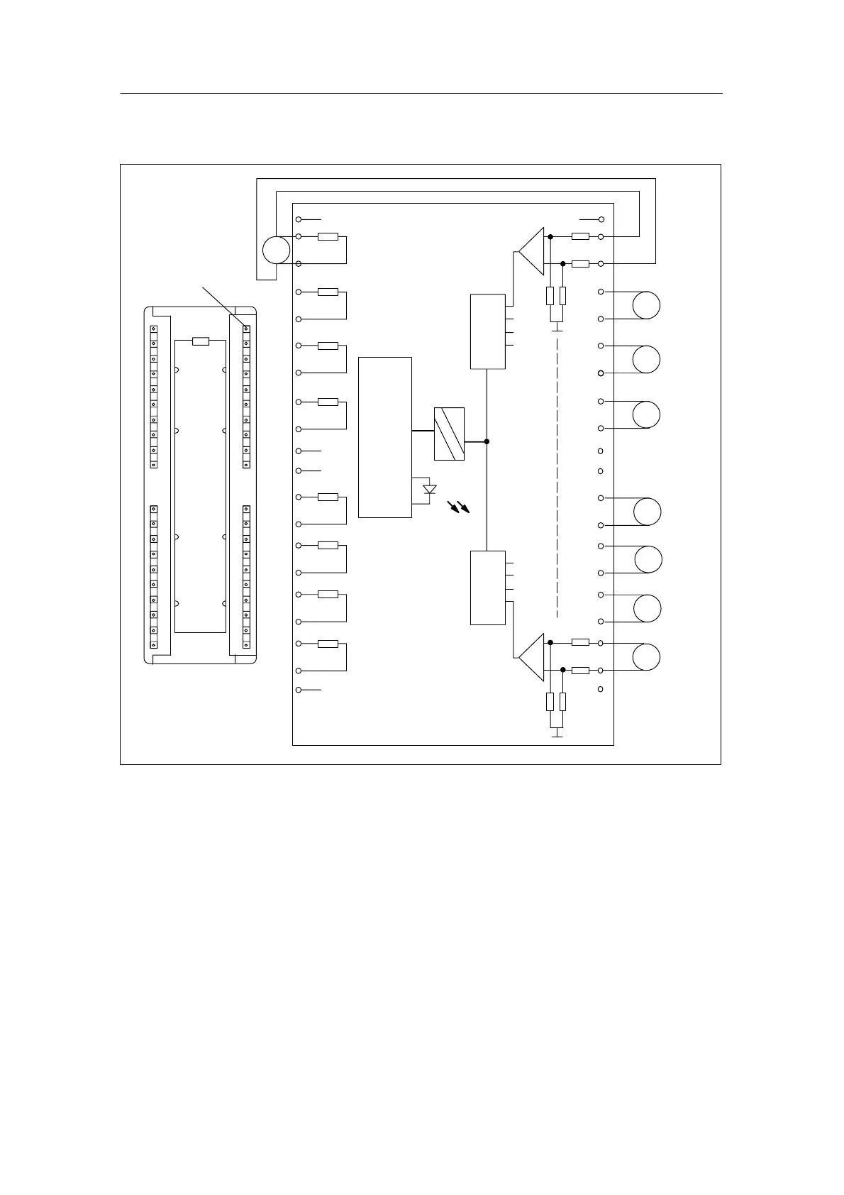
Terminal connection diagram and block diagram of the SM 331; AI 8 x 16 bits
2
20
1
3
250 OHM
4
5
250 OHM
6
7
250 OHM
8
9
250 OHM
10
11
12
13
250 OHM
14
15
250 OHM
16
17
250 OHM
18
19
250 OHM
A
+
–
CHO
V
+
–
CH1
V
+
–
CH2
V
+
–
CH3
V
+
–
CH4
V
+
–
CH5
V
+
–
CH6
V
+
–
CH7
21
29
26
27
24
25
22
23
33
32
35
34
37
36
39
38
28
40
31
30
ADC
ADC
Back-
plane
bus
interface
module
SF
Isolation
SF
Fault indicator – red
Figure 4-33 Module view and block diagram of the analog input module SM 331; AI 8 x 16 bits
Please note that in Figure 4-33, channel 0 is configured for current measurement
and channel 7 for voltage measurement.

 Loading...


