A-6
Programmable Logic Controllers S7-300 Module Data
A5E00105505-03
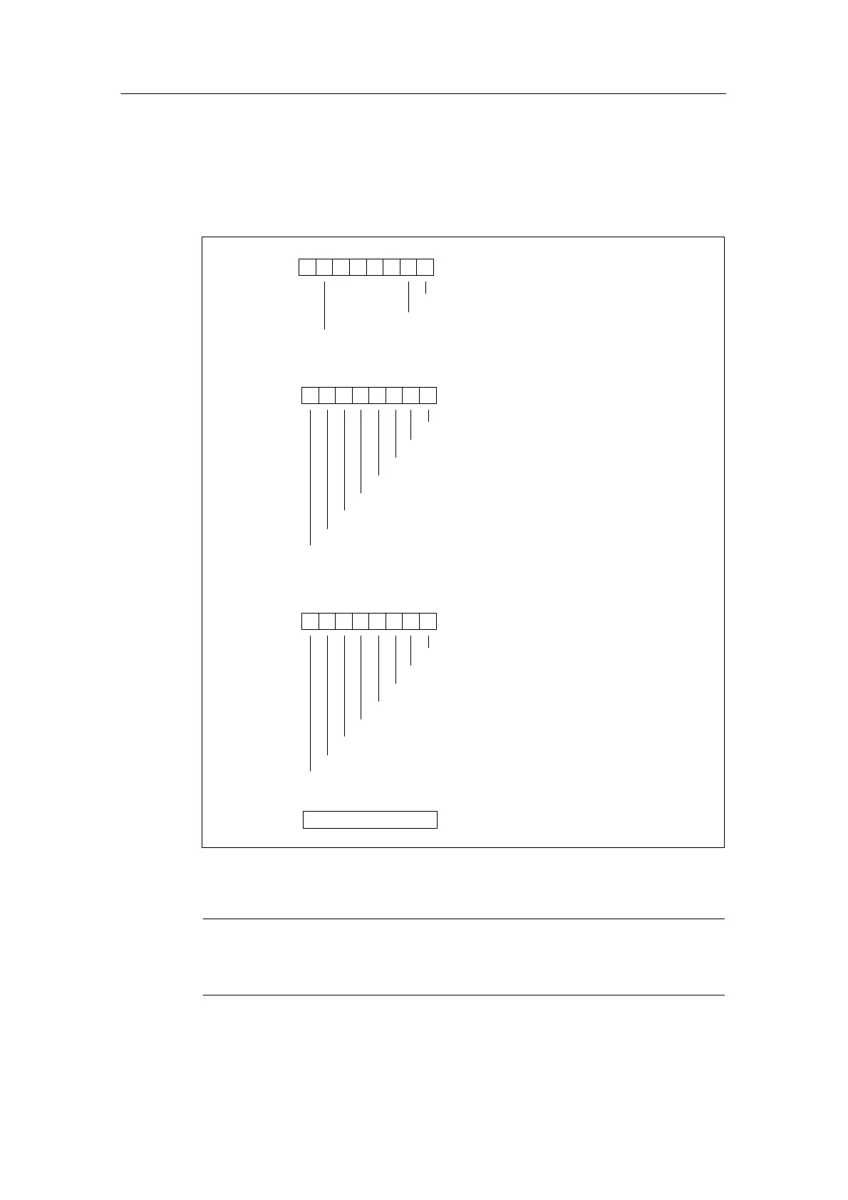
Data record 1 structure
The figure below shows the structure of data record 1 for the parameters of the
digital output modules.
You activate a parameter by setting the corresponding bit in byte 0 to “1”.
Byte 0
76 0
1
Hold last valid value
Apply substitute value
Diagnostics interrupt enable
Byte 3
Not relevant
Byte 1
76 054321
Byte 2
76 0
Enable substitute value 1 on channel 15
54321
Substitute value
Substitute value
Enable substitute value 1 on channel 7
Enable substitute value 1 on channel 6
Enable substitute value 1 on channel 5
Enable substitute value 1 on channel 4
Enable substitute value 1 on channel 3
Enable substitute value 1 on channel 2
Enable substitute value 1 on channel 1
Enable substitute value 1 on channel 0
Enable substitute value 1 on channel 8
Enable substitute value 1 on channel 9
Enable substitute value 1 on channel 10
Enable substitute value 1 on channel 11
Enable substitute value 1 on channel 12
Enable substitute value 1 on channel 13
Enable substitute value 1 on channel 14
Behavior on CPU STOP
Figure A-2 Data Record 1 for Parameters of the Digital Output Modules
Note
You should only enable the parameters in byte 0, “Hold last valid value” and
“Enable substitute value” as an alternative.
 Loading...


