A-8
Programmable Logic Controllers S7-300 Module Data
A5E00105505-03
Data record 1 structure
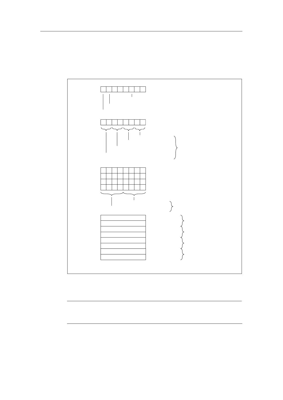
The figure below shows the structure of data record 1 for the parameters of the
analog input modules.
You activate a parameter by setting the corresponding bit in byte 0 and 1 to “1”.
Byte 0
76 0
Diagnostics interrupt enable
Limit value interrupt enable
Byte 1
Channel group 0
Channel group 1
Channel group 3
Channel group 2
Interference suppression
Byte 2
Byte 3
Byte 4
Byte 5
7043
Measurement channel group 0
Measurement channel group 2
Measurement channel group 1
Measurement channel group 3
Measuring
Range
Measuring Method
Upper limit value channel
group 0; channel 0
Lower limit value channel
group 0; channel 0
Upper limit value channel
group 1; channel 2
Lower limit value channel
group 1; channel 2
Low-Order Byte
Low-Order Byte
Low-Order Byte
Low-Order Byte
High-Order Byte
High-Order Byte
High-Order Byte
High-Order Byte
Byte 6
Byte 7
Byte 8
Byte 9
Byte 10
Byte 11
Byte 12
Byte 13
See Table A-6
See Table A-5
Note: For the channel groups, only one limit value
for channel 1 is ever set.
Cycle end interrupt enable
2
Figure A-3 Data Record 1 for Parameters of the Analog Input Modules
Note
The representation of the limit values matches the analog value representation
(see Chapter 4). Please observe the range limits when setting the limit values.