A-16
Programmable Logic Controllers S7-300 Module Data
A5E00105505-03
Operating modes of the SM 331; AI 8 RTD
The table below contains the codes for the different operating modes, which you
enter in byte 0 of data record 128 (refer to Figure A-5).
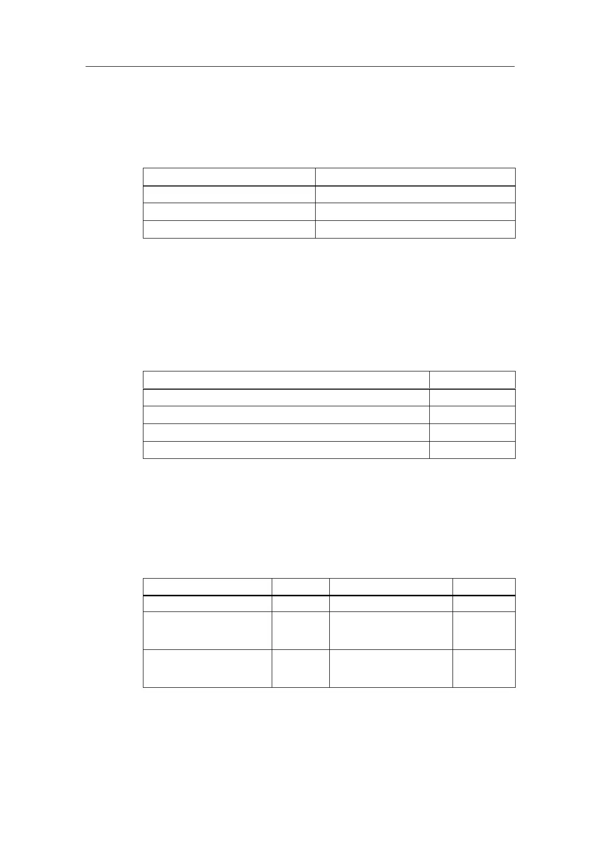
Table A-8 Codes of Operating Modes of the SM 331; AI 8 x RTD
Module filtering mode Code
8 channels hardware filter 2#00000000
8 channels software filter 2#00000001
4 channels hardware filter 2#00000010
Interference frequency suppression of the SM 331; AI 8 x RTD
The table below contains the codes for the different frequencies, which you enter in
byte 1 of data record 128 (refer to Figure A-5). Note that the settings 50 Hz, 60 Hz
and 400 Hz only apply to 8-channel software filter mode. The setting 50, 60 and
400 Hz only applies to 8-channel and 4-channel hardware filter mode.
Table A-9 Interference Frequency Suppression Codes for SM 331; AI 8 x RTD
Interference Suppression Code
400 Hz 2#00
60 Hz 2#01
50 Hz 2#10
50/60/400 Hz 2#11
Measuring methods and measuring ranges of the SM 331; AI 8 x RTD
The table below contains all the measuring methods and measuring ranges of the
module and its codes. You must enter these codes in the corresponding bytes of
data record 128 (refer to Figure A-3).
Table A-10 Codes for the Measuring Ranges of the SM 331; AI 8 x RTD
Measuring Method
Code Measuring Range Code
Deactivated 2#0000 Deactivated 2#0000
Resistance, four-conductor
connection
2#0100 150
300
600
2#0010
2#0100
2#0110
Resistance, three-conductor
connection
2#0101 150
300
600
2#0010
2#0100
2#0110
 Loading...


