EasyManuals Logo

Siemens SIMATIC S7-300 Module data Reference Manual

Siemens SIMATIC S7-300 Module data
574 pages
To Next Page IconTo Next Page
To Previous Page IconTo Previous Page
Page #499 background imageLoading...
Page #499 background image
Parameter Sets for Signal Modules
A-31
Programmable Logic Controllers S7-300 Module Data
A5E00105505-03
Structure of data record 1
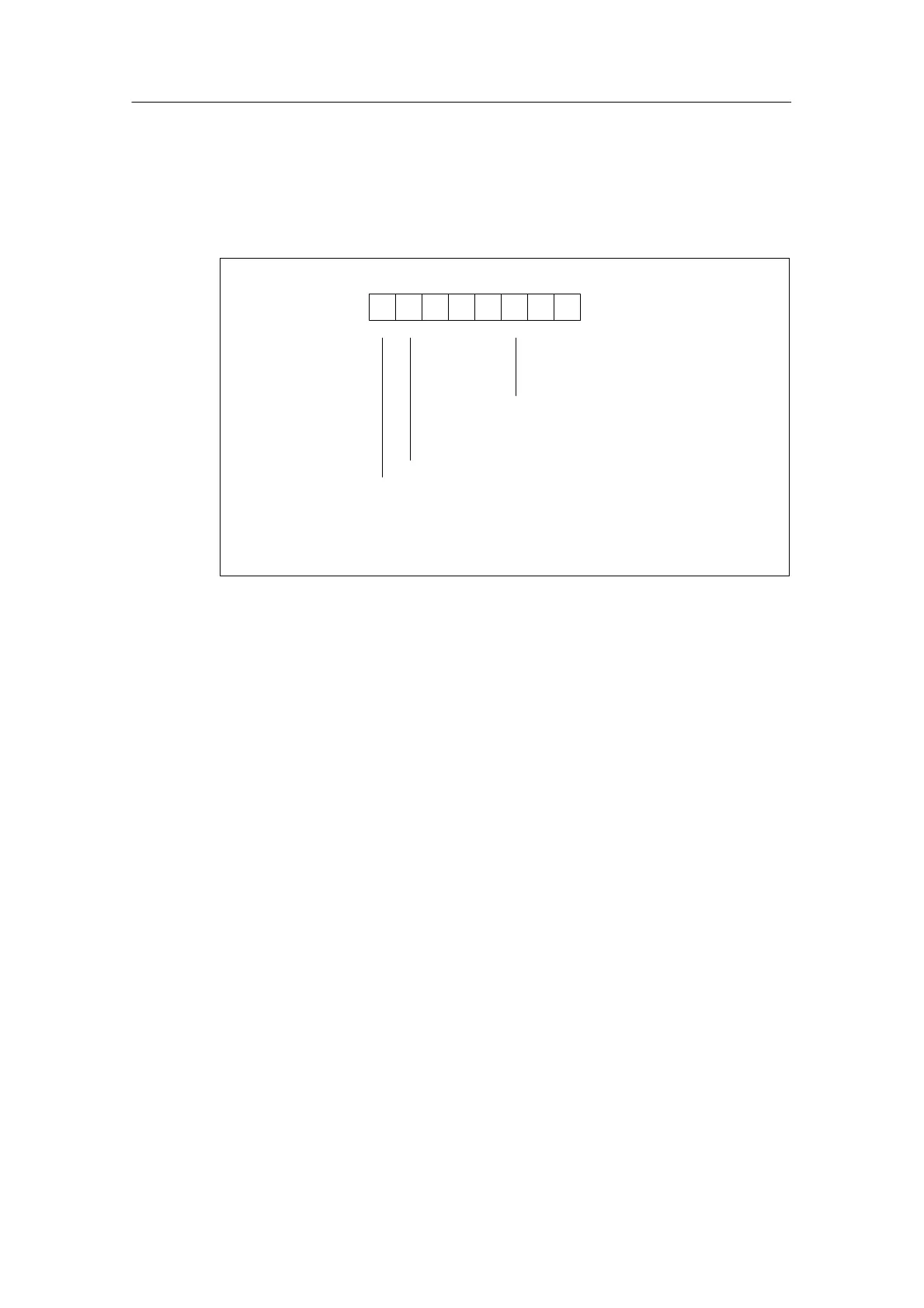
Figure A-13 shows the structure of data record 1 for the parameters of the isolated
analog input module SM 331; AI 8 x 16 bits.
You can activate a parameter by setting the corresponding bit in byte 0 to “1”.
Byte 0
Bit number
76543210
Cycle end interrupt enable
Diagnostics interrupt enable
Limit value interrupt enable
Bytes 1 to 13 are not assigned
Figure A-13 Data Record 1 of the Parameters for SM 331; AI 8 x 16 bits

Table of Contents

Other manuals for Siemens SIMATIC S7-300 Module data

Questions and Answers:

Question and Answer IconNeed help?

Do you have a question about the Siemens SIMATIC S7-300 Module data and is the answer not in the manual?

Siemens SIMATIC S7-300 Module data Specifications

General IconGeneral
SeriesS7-300
ManufacturerSiemens
Protection ClassIP20
SystemSIMATIC S7-300
Digital InputsVaries by module
Digital OutputsVaries by module
Analog InputsVaries by module
Analog OutputsVaries by module
Central Processing UnitVaries by CPU model
Supply Voltage24V DC or 120/230V AC
CPU TypeVaries (e.g., CPU 312, CPU 315, etc.)
MemoryVaries by CPU model
Communication InterfacesMPI, PROFIBUS
Programming LanguagesLAD, FBD, STL, SCL, GRAPH
Operating Temperature0°C to 60°C
Storage Temperature-40°C to 70°C
Relative Humidity10% to 95% (non-condensing)

Related product manuals