A-40
Programmable Logic Controllers S7-300 Module Data
A5E00105505-03
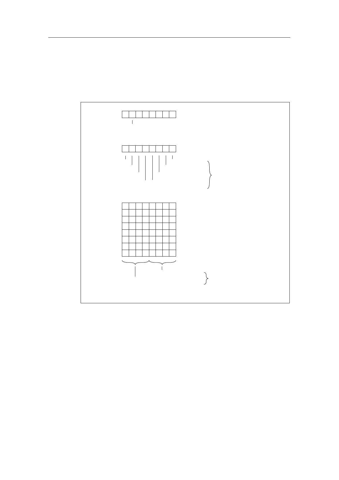
Structure of data record 1
The diagram below shows the structure of data record 1 of the parameters of the
SM 332; AO 8 x 12 bits.
You activate the diagnostics interrupt enable by setting the corresponding bit in
byte 0 to “1”.
Byte 0
76 0
Byte 1
Channel 0
Channel 1
Channel 3
Channel 2
Behavior on CPU STOP
Byte 2
Byte 3
Byte 4
Byte 5
7043
Output channel 0
Output channel 2
Output channel 1
Output channel 3
Output Range
Output type
Bytes 10 to 13 are not assigned
70321
Diagnostics interrupt enable
See Table A-31
0 = Outputs
de-energized
1 = Hold last value
Channel 4
Channel 5
Channel 7
Channel 6
Byte 6
Byte 7
Byte 8
Byte 9
Output channel 4
Output channel 6
Output channel 5
Output channel 7
465
Figure A-18 Data Record 1 for Parameters of the Analog Output Modules