EasyManuals Logo

Siemens SIMATIC S7-300 Module data Reference Manual

Siemens SIMATIC S7-300 Module data
574 pages
To Next Page IconTo Next Page
To Previous Page IconTo Previous Page
Page #510 background imageLoading...
Page #510 background image
A-42
Programmable Logic Controllers S7-300 Module Data
A5E00105505-03
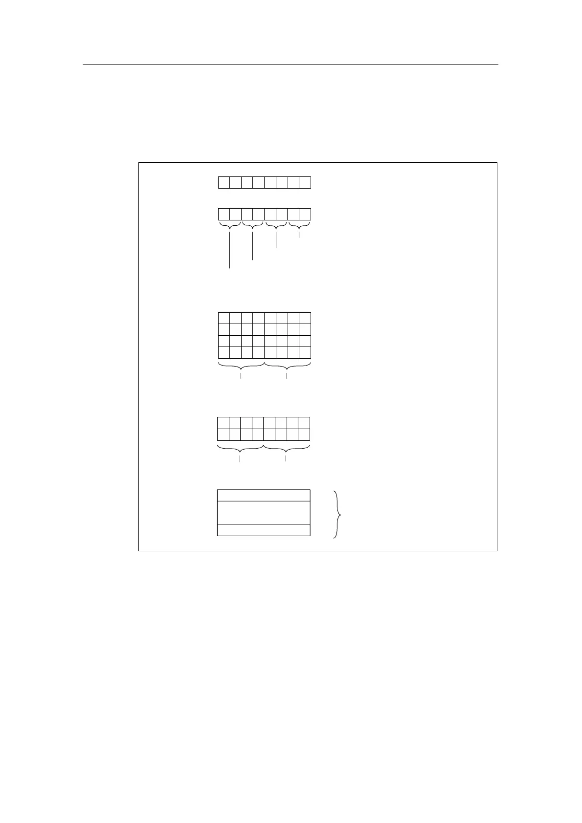
Structure of data record 1
The figure below shows the structure of data record 1 for the parameters of the
analog input/output modules.
You activate a parameter by setting the corresponding bit in byte 0 and 1 to “1”.
Byte 0
70
Byte 1
Channel 0
Channel 1
Channel 3
Channel 2
Reset Time
Byte 2
Byte 3
Byte 4
Byte 5
7043
Meas. channel 0
Meas. channel 2
Meas. channel 1
Meas. channel 3
Measuring
Range
Measuring
Method
70
Not relevant
:
Byte 8
:
Byte 13
Byte 6
Byte 7
7043
Output channel 0
Output channel 1
Output RangeOutput type
Set the same parameters for
all channels.
Not relevant
Figure A-19 Data Record 1 for Parameters of the Analog Input/Output Modules

Table of Contents

Other manuals for Siemens SIMATIC S7-300 Module data

Questions and Answers:

Question and Answer IconNeed help?

Do you have a question about the Siemens SIMATIC S7-300 Module data and is the answer not in the manual?

Siemens SIMATIC S7-300 Module data Specifications

General IconGeneral
SeriesS7-300
ManufacturerSiemens
Protection ClassIP20
SystemSIMATIC S7-300
Digital InputsVaries by module
Digital OutputsVaries by module
Analog InputsVaries by module
Analog OutputsVaries by module
Central Processing UnitVaries by CPU model
Supply Voltage24V DC or 120/230V AC
CPU TypeVaries (e.g., CPU 312, CPU 315, etc.)
MemoryVaries by CPU model
Communication InterfacesMPI, PROFIBUS
Programming LanguagesLAD, FBD, STL, SCL, GRAPH
Operating Temperature0°C to 60°C
Storage Temperature-40°C to 70°C
Relative Humidity10% to 95% (non-condensing)

Related product manuals