Section04ENGINE
Subsection 01 (593, 593 HO, 593 HO SDI AND 793 HO ENGINE TYPES)
CAUTION: Always install new mono-hook cir-
clips. If circlip installation fails at the first at-
tempt, always retry with a new one because,
on a second attempt, the circlip will lose its nor-
mal retaining capabilities.
CAUTION: Circlips must not move freely after
installation; if so, replace them.
Before inserting piston in cylinder, lubricate the
cylinder with new injection oil or equivalent.
Cylinder Head Cover, Cylinder Head
and Cylinder
Make sure parts sealing surfaces are flat. Re-
fer to LEAK TEST AND ENGINE DIMENSION
MEASUREMENT and look for CYLINDER HEAD
WARPAGE.
Clean cylinders and crankcase mating surfaces
with Loctite Chisel (P/N 413 708 500).
Coat crankcase mating surface with Loctite 518
(P/N 293 800 038). Choose the right gasket thick-
ness according to combustion chamber volume.
Refer to LEAK TEST AND ENGINE DIMENSION
MEASUREMENT. Install it on crankcase. Coat
gasket with Loctite 518.
CAUTION: Always install a gasket of the proper
thickness. Failure to do so may cause detona-
tion and severe engine damage.
Before inserting piston in cylinder, lubricate the
cylinder with new injection oil or equivalent.
Install cylinders. Do not tighten.
Install new rubber ring and round O-rings on each
cylinder.
NOTE: Carefully clean screws before reinstalla-
tion, specifically under screw head.
Install exhaust manifold with gaskets. Do not
tighten yet.
Torque cylinder screws in a crisscross sequence
as per the following table.
M8 29 N•m(21lbf•ft)
M10 40 N•m(29lbf•ft)
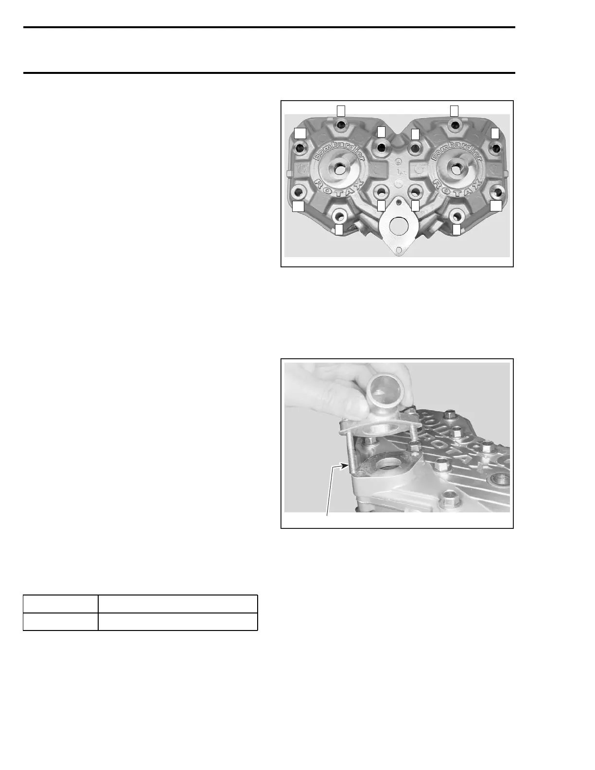
At assembly, torque cylinder head screws to 29
N•m(21lbf•ft) in the following illustrated se-
quence.
6
A32C9EA
4 2
8
12
10
11 9
1
3
5 7
TYPICAL
Tighten exhaust manifold bolts in a criss-cross se-
quence.
Apply Loctite 243 (P/N 293 800 060) on screws
threads. Install outlet socket and tighten screws.
Note position of longer screw.
1
A32C19A
1. Longer screw
Reed Valve
All Engine Types except 793 HO
Blades have a curved shape. Install with their
curve facing reed block.
With blade stopper no. 29 removed, check reed
valve for proper tightness. There must not be any
play between blade and valve body when exerting
a finger pressure on blade at blade stopper loca-
tion.
98 mmr2004-Rev

 Loading...
