Section 03 TROUBLESHOOTING
Subsection 04 (ELECTRICAL SYSTEM)
A32E3US
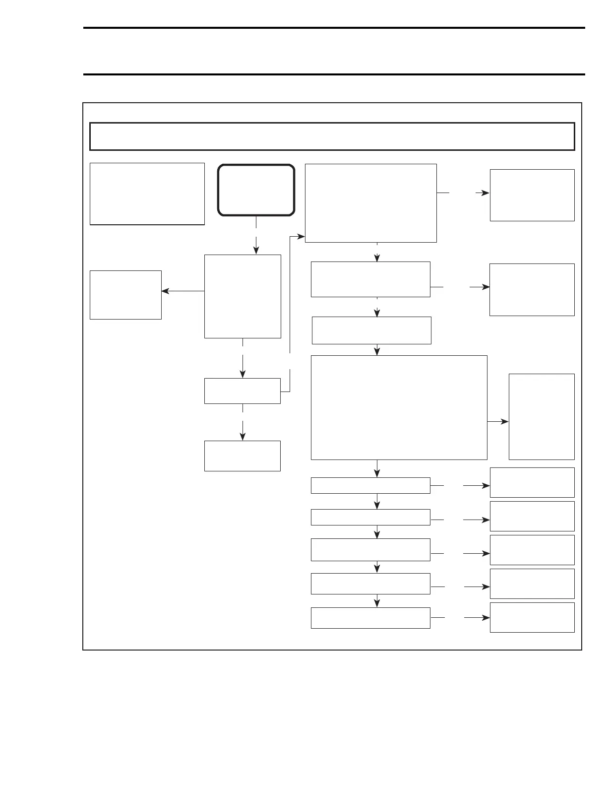
Install supply cable to diagnostic connector
of snowmobile as per shop manual
procedure. Do not connect any supply
voltage before starting the vehicle. Start
cranking over the engine. While the engine
is being cranked, connect 12 V supply to the
2-position housing of the supply cable.
Respect polarity +12 V to RED wire, ground
to BLACK wire, and check for spark.
Fault is on the motor side of
ignition system. Continue
with the following.
Check for
spark at
spark plug
No spark
Check that tether
DESS cord switch,
ignition switch and
engine cut-out
switch are in place
and in the run
position.
One of the
switches was
left in the off
position.
No spark
Replace spark plug
and retest.
Spark returns
Spark plug was
at fault.
OK
360 W - 2 CYLINDER
OK
SYMPTOM
NO START AND
NO SPARK
Check stator ignition
generator coil.
Replace stator
and retest.
OK
Check ignition coil.
Replace spark plug
cap and retest. w
OK
Replace ignition coil
and retest.
OK
Check connection 11-DA, 11-DE,
11-DC from MPEM.
Replace MPEM
and retest.
OK
No
good
Check trigger coil.
Replace trigger coil
and retest.
OK
No
good
No
good
No
good
No
good
Disconnect the 6-HC connector
that has the BLACK/WHITE,
WHITE/GRAY, and the
BLACK/GREEN wires to the tether
cord switch. Place a jumper wire
between the BLACK/WHITE and
the BLACK/GREEN wires and
retest for spark.
Disconnect the 6-HG connector
that has the BLACK/YELLOW
and the BLACK wires and
retest for spark.
No spark
No spark
Fault is in the tether
cord switch. Inspect
and retest.
OK
Fault is in the
engine cut-out
switch. Inspect
and retest.
OK
Spark
returns
Spark
returns
Spark
returns
No
spark
IGNITION SYSTEM DIAGNOSTIC FLOW CHART
Check spark plug cap.
OK
Spark
returns
No spark
Fault is in the
charging system.
Refer to the
charging system
diagnostic flow
chart to find
the problem.
mmr2004-Rev 65

 Loading...
