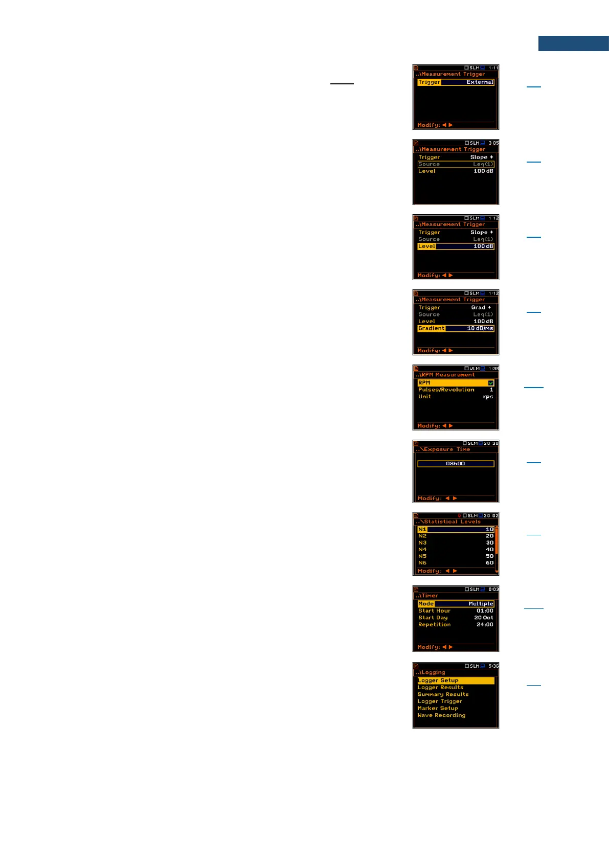
Type of trigger that starts the measurement/integration
when the trigger signal appears on the pin 2 of the I/O
socket of the instrument. After the measurement/
integration start from the trigger, the measurement/
integration will continue by the Integration Period.
Measured result that is compared with the threshold
value (Level) for triggering – RMS measured in the first
profile: Leq(1) in sound modes and RMS(1) in vibration
modes.
Threshold level of Source for triggering condition
fulfilment.
Threshold level of the Source gradient for triggering
condition fulfilment.
Screen that enables configuring measurement of the
rotation per minute/second. To perform the RPM
measurement the RPM probe should be connected to the
I/O socket.
Screen that enables setting a duration of worker’s
exposition to the noise. This duration is considered in
LEPd calculations.
Chapter
4.8
Appendix D
D.1.2
Screen that enables setting a boundary level (Lnn)
surpassed by the temporary noise level values in not
more than nn% of the observation period. The user can
define ten statistical levels, named from N1 to N10, to be
calculated, displayed and saved in the files together with
the main results.
Chapter
4.9
Appendix D
D.4
Screen that enables configuring automatic switching On
the instrument and performing the measurement on the
programmed time with defined setup. Timer can be
Single or repeatable (Multiple).
After every timer cycle, the instrument automatically
switches itself off.
Screen that enables configuring saving of the
Summary Results, Logger Results, markers and a
waveform signal in files with the use of the next screens:
Logger Setup, Logger Results, Summary Results,
Logger Trigger, Marker Setup and Wave Recording.