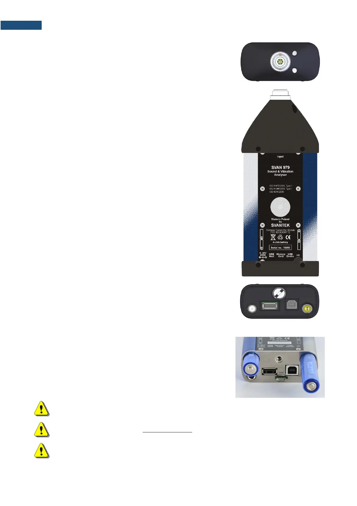
Top cover of the instrument
The measurement input is placed in the centre of the instrument’s top cover.
It is the Lemo-7 compatible socket.
The SV 17 microphone preamplifier has a specially designed matching plug
and a locking screw to secure the preamplifier to the meter body.
The accelerometers have to be connected to the instrument also using the
Lemo-7 connector. After connecting the preamplifier or the accelerometer
cable to the measurement input, the screw should be tightened to light
resistance only.
Do not over tighten this connector.
It is not necessary to remove this preamplifier from the top of the instrument
unless the meter is in a calibration laboratory as it is always used close
coupled to the meter body.
The full description of the signals connected to the sockets is given in
Appendix C.
Bottom cover of the instrument
In the bottom cover there are four sockets, placed from the right to the left
as follows: 6-24V, USB Host, USB Device and I/O.
The USB Device 1.1 interface is the serial interface working with 12 MHz
clock. Thanks to its speed, it is widely used in all PC. In the instrument, the
standard 4-pin socket is used and described in detail in Appendix C.
The USB Host 1.1 interface can be used to connect an external USB
Memory Stick or USB hard disk, enabling the device to register virtually
infinite sequence of measurement results.
The additional multi-purpose input / output socket, called I/O, is a two-pin
LEMO socket. On this socket, in case the Analogue Output functionality is
selected, the signal from the input of the analogue / digital converter (before
any frequency correction) is available. This signal can be recorded using
magnetic recorder or observed on the oscilloscope. The Digital Input is
another functionality that serves as the external trigger to the instrument,
while the Digital Output is used to generate the trigger pulse or alarm pulse
from the instrument.
You can connect an external DC power 6-24V adapter to the 6-24V socket
located on the bottom cover of the instrument. The current consumption
depends on the voltage of the power supplier.