RemovingandInstallingtheTractionPumpDriveAssembly
g301635
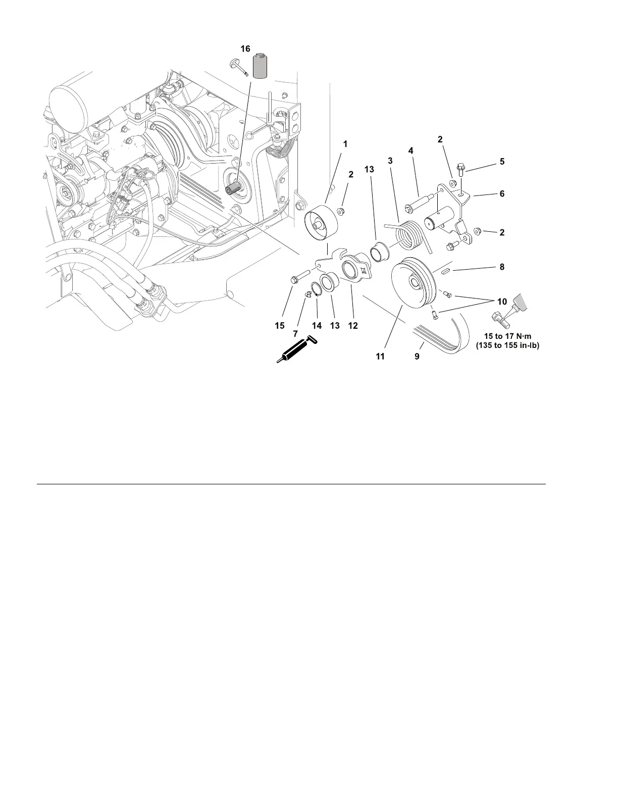
Figure50
1.Idlerpulley
7.Greasetting13.Flangebushing(2each)
2.Flangelocknut(5each)
8.Key14.Retainingring
3.Torsionspring9.Drivebelt
15.Capscrew
4.Shoulderbolt10.Squareheadsetscrew(2each)16.Pumpshaft
5.Capscrew(3each)
11.Pumppulley
6.Idlerpivot12.Idlerarm
1.Parkthemachineonalevelsurface,lowerthecuttingunit(orattachment),
engagetheparkingbrake,setthekeyswitchtotheOFFpositionandremove
thekeyfromthekeyswitch.
2.Raisethehood.
3.Usea1/2inchsquaredriveonthehydraulicpumpdrivebeltidlerarmto
relievethebelttensionandremovethebeltfromthepumppulley.
4.Allowtheidlerarmtorestwithnospringload.
5.Disassemblythepumpdrivecomponentsifnecessary.
6.Inspectthedrivebelt,idlerarmbushings,andidlerpulley(bearings)and
replaceifnecessary.
7.Ifthepumppulleyisremoved:
A.Installthekeyandapplyathincoatofanti-seizelubricanttothepump
shaftbeforeinstallingthepumppulley.
B.Alignthepulleywiththedrivebeltgroovesontheenginestubshaft.
C.Usemediumstrengththreadlockeronthepulleysetscrewsandtighten
thesetscrewsfrom15to17N·m(135to155in-lb).
HydraulicSystem:ServiceandRepairs
Page5–68
Groundsmaster
®
3200,3300and3310
19240SLRevA