CANbus
ThemachinecontrollerscommunicatewitheachotheronaControllerArea
Network(CAN)bussystem.Usingthisnetworkallowsfullintegrationofallthe
differentelectricalcomponentsofthemachine,allowingthemtooperatetogether
asone.TheCANbussystemreducesthenumberofelectricalcomponentsand
connectionsusedonthemachineandallowsthenumberofwiresinthewire
harnesstobesignicantlyreduced.
Formodel31900,31901,31907and31909machines,theTDMcontrolleristhe
onlycontrollerontheCANbuspresently.Formodel31902and31903machines,
theTDMcontrollerandtheYanmarengineECUaretheonlycontrollersonthe
CANbuspresently.Additionalcontrollers(forattachments)maybeadded
totheCANbusinthefuturethroughtheexpansionportconnectorand/orthe
telematicsconnector.
EachofthecomponentsthatiscontrolledbytheCANbuslinkonlyneedsfour
(4)wirestooperateandcommunicatetothesystem:CANHigh,CANLow,
powerandground.ThekeyswitchneedstobeintheRUNorSTARTposition
forthecomponentsonthenetworktobeactivated.
Twospeciallydesigned,twistedwiresformtheCANbus.Thesewiresprovidethe
datapathwaysbetweenthecomponentsonthenetwork.Theengineeringterm
forthesecablesareCANHighandCANLow.TheCANbuswiresarered/white
(CAN-High)andblack/white(CANLow).AteachendoftheCANbusisa120
ohmterminationresistor;refertoCANbusT erminatorResistors(page6–56).
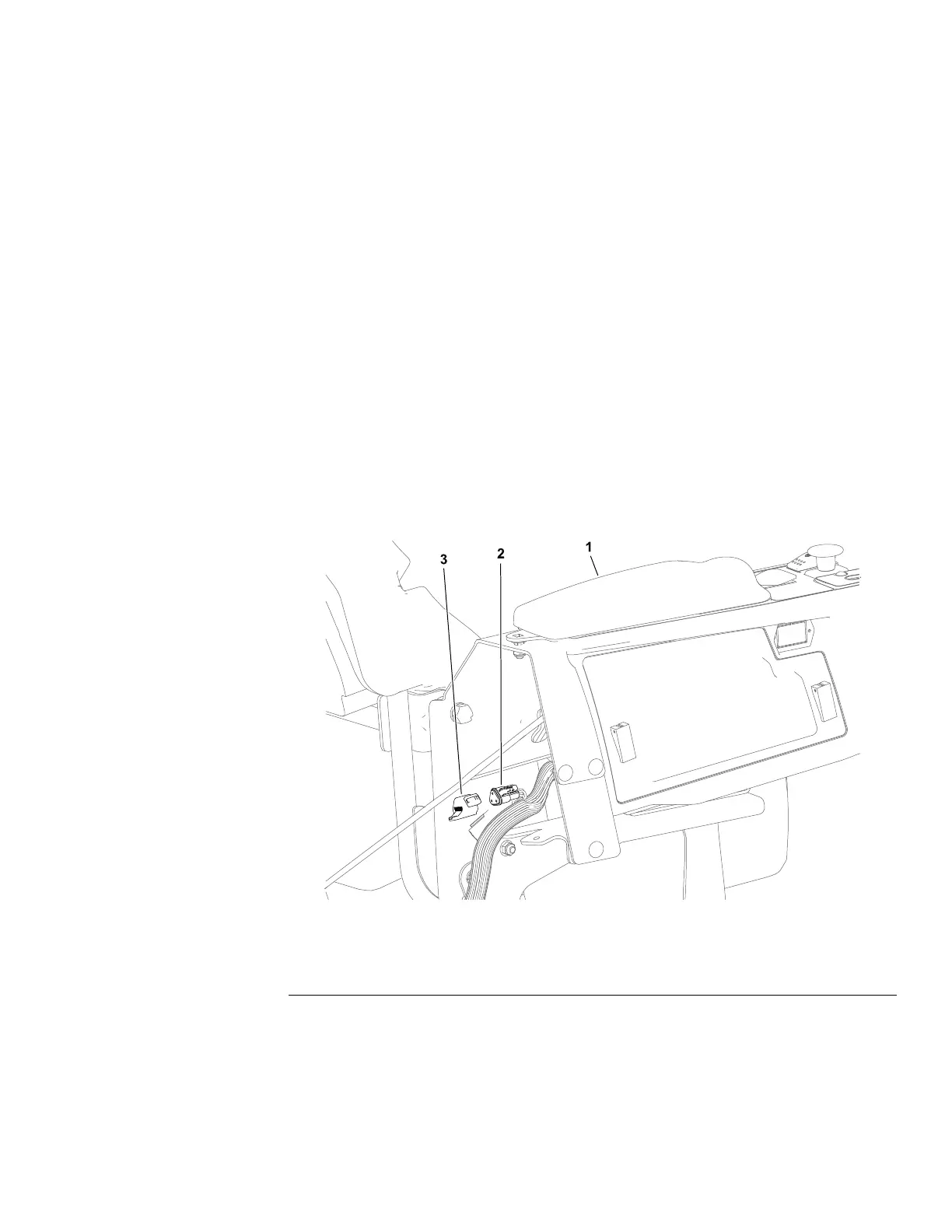
TestingtheCANbus
g305596
Figure84
1.Operator’sconsole3.Cover
2.DIAGconnector
1.Parkthemachineonalevelsurface,lowerthecuttingunit(orattachment),
engagetheparkingbrake,setthekeyswitchtotheOFFpositionandremove
thekeyfromthekeyswitch.
2.TheT oroDIAGconnectorispartoftheCANbusandislocatedattherear
oftheoperator’sconsole.Removetheconnectorcoverfromthemachine
wireharnessanduseamultimeter(ohmssetting)tochecktheT oroDIAG
connector.
Groundsmaster
®
3200,3300and3310
Page6–17
ElectricalSystem:TestingtheElectricalComponents
19240SLRevA