LiftArms
g314906
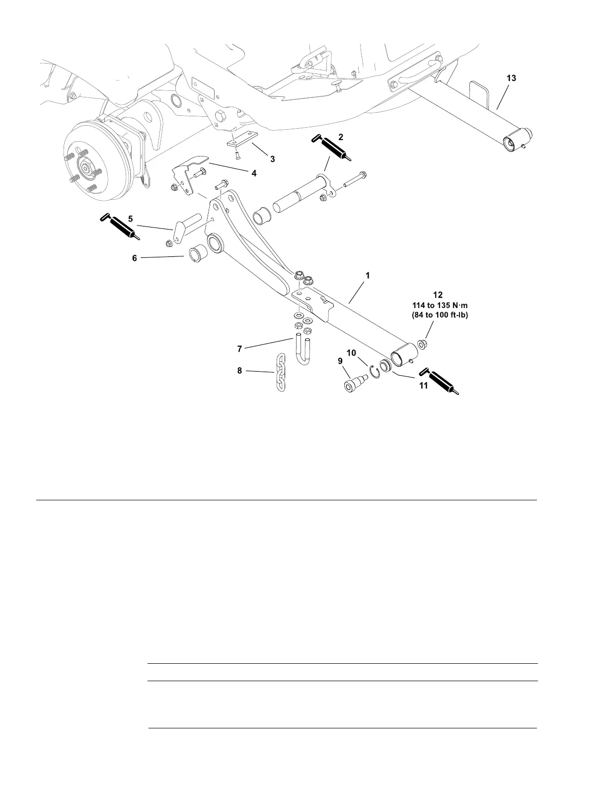
Figure129
1.Liftarm–left6.Flangebushing(2each)11.Sphericalbearing
2.Liftarmpivotpin7.U-bolt(2each)
12.Flangenut
3.Bumperpad
8.Heightofcut(HOC)chain(2each)13.Liftarm–right
4.Switchsensingplate
9.Shoulderbolt
5.Liftcylinderpivotpin
10.Retainingring
Note:Thesphericalbearingsatthecuttingunitendoftheliftarmshavealight
presstandcanbereplacedwithoutremovingtheliftarmsfromthemachine.
RemovingtheLiftArms
1.Removethecuttingunitfromthemachine;refertothecuttingunitOperator’s
Manual.
2.Removethefrontwheelnexttotheliftarmbeingremoved;refertoRemoving
andInstallingtheWheels(page7–5).
3.Supporttheliftarmandtheliftcylinderandremovethepinfromtherodend
ofthecylinder.Donotallowthecylindertohangmythehydraulichoses.
IMPORTANT
Donotcontactorscratchthefaceofthecuttingunithightrimheight
switchwhenworkingneartheswitch.
Chassis:ServiceandRepairs
Page7–30
Groundsmaster
®
3200,3300and3310
19240SLRevA