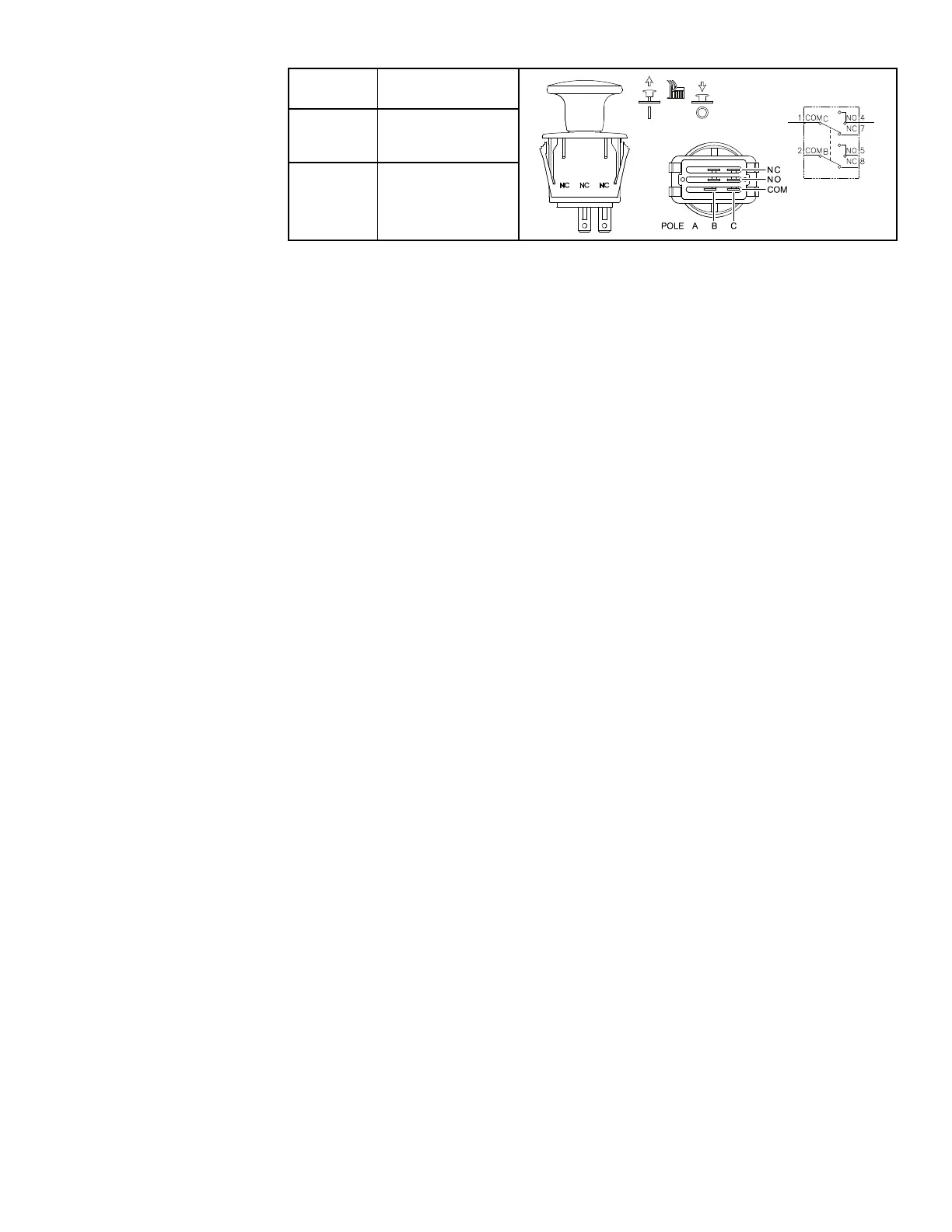
PTOSwitch
POSITIONCLOSED
CIRCUITS
OFF
(DOWN)
COMB+NCB
COMC+NCC
ON(UP)COMB+NOB
COMC+NOC
Thepowertakeoff(PTO)switchislocatedontheoperator’sconsole.This
switchispulleduptoengagethePTOshaftandpusheddowntodisengage
thePTOshaft.
TheTDMdisplay/controllermonitorsthepositionofthePTOswitch.Using
informationfromthePTOswitchandotherinputs,theTDMcontrollerenergizes
theelectricPTOclutchcoiltoengagethePTOshaft.
TestingthePTOSwitch
ThePTOswitchanditscircuitwiringcanbetestedusingtheTDM
display/controller;refertoUsingtheTDMDisplay/ControllerScreensfor
Troubleshooting(page3–12).Iftestingdeterminesthattheswitchandcircuit
wiringarenotfunctioningcorrectly,proceedwiththefollowingtestprocedure:
1.Parkthemachineonalevelsurface,lowerthecuttingunit(orattachment),
engagetheparkingbrake,setthekeyswitchtotheOFFpositionandremove
thekeyfromthekeyswitch.
2.Disconnectthebatterynegative(-)cableatthebattery;refertoRemoving
andInstallingtheBattery(page6–64).
3.Removetheoperator’sconsolecovers;refertoRemovingandInstallingthe
Operator’sConsoleCovers(page7–23).
4.Disconnectthewireharnessconnectorfromtheswitchandremovethe
switchfromtheconsoleifnecessary.Checktheswitchandtheharness
connectorfordamageorcorrosionandcleanorrepairifnecessary.
5.Useamultimeter(ohmssetting)andtheprecedingtabletodetermine
whethercontinuityexistsbetweenthevariousterminalsforeachswitch
position.
6.Replacetheswitchifnecessary.
7.Iftheswitchtestscorrectlyandacircuitproblemstillexists,checkthewire
harnesses;refertoAppendixA(pageA–1).
8.Installtheswitchandconnectthewireharnessaftertesting.
9.Installtheconsolecovers.
10.Connectthebatterynegative(-)cableatthebattery.
Groundsmaster
®
3200,3300and3310
Page6–23
ElectricalSystem:TestingtheElectricalComponents
19240SLRevA