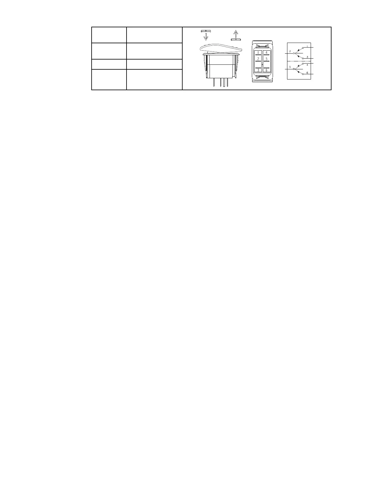
Lift/LowerSwitch
POSITIONCLOSED
CIRCUITS
INCREASE
SPEED
2+3,5+6
NEUTRAL
NONE
DECREASE
SPEED
2+1,5+4
Thelift/lowerswitchislocatedontheoperator’sconsole.Whenthefrontof
theswitchisdepressed,theliftarmswilllower.Whentherearoftheswitch
isdepressed,theliftarmswilllift.Whenraisingtheliftarms,theliftarmswill
remaininpositioniftheswitchisreleased.Theenginemustberunningtoallow
theliftarmstoberaised.
TheTDMdisplay/controllermonitorssignalsfromthelift/lowerswitch.Whenthe
frontoftheswitchisdepressed,theTDMdisplay/controllerenergizessolenoid
valvecoilSV1causingthevalvetoshiftandtheliftcylindertoextendtoraisethe
liftarms.Whentherearoftheswitchisdepressed,theTDMdisplay/controller
energizessolenoidvalvecoilSV2causingthevalvetoshiftallowingthehydraulic
uidintheliftcylindertoescape.Theweightofthecuttingunit(orattachment)
retractstheliftcylindertolowertheliftarms.
TestingtheLift/LowerSwitch
Thelift/lowerswitchanditscircuitwiringcanbetestedusingtheTDM
display/controller;refertoUsingtheTDMDisplay/ControllerScreensfor
Troubleshooting(page3–12).Iftestingdeterminesthattheswitchandcircuit
wiringarenotfunctioningcorrectly,proceedwiththefollowingtestprocedure:
1.Parkthemachineonalevelsurface,lowerthecuttingunit(orattachment),
engagetheparkingbrake,setthekeyswitchtotheOFFpositionandremove
thekeyfromthekeyswitch.
2.Disconnectthebatterynegative(-)cableatthebattery;refertoRemoving
andInstallingtheBattery(page6–64).
3.Removetheoperator’sconsolecovers;refertoRemovingandInstallingthe
Operator’sConsoleCovers(page7–23).
4.Disconnectthewireharnessconnectorfromtheswitchandremovethe
switchfromtheconsoleifnecessary.Checktheswitchandtheharness
connectorfordamageorcorrosionandcleanorrepairifnecessary.
5.Useamultimeter(ohmssetting)andtheprecedingtabletodetermine
whethercontinuityexistsbetweenthevariousterminalsforeachswitch
position.
6.Replacetheswitchifnecessary.
7.Iftheswitchtestscorrectlyandacircuitproblemstillexists,checkthewire
harnesses;refertoAppendixA(pageA–1).
8.Installtheswitchandconnectthewireharnessaftertesting.
9.Installtheconsolecovers.
10.Connectthebatterynegative(-)cableatthebattery.
ElectricalSystem:TestingtheElectricalComponents
Page6–24
Groundsmaster
®
3200,3300and3310
19240SLRevA