SteeringCircuit
g298128
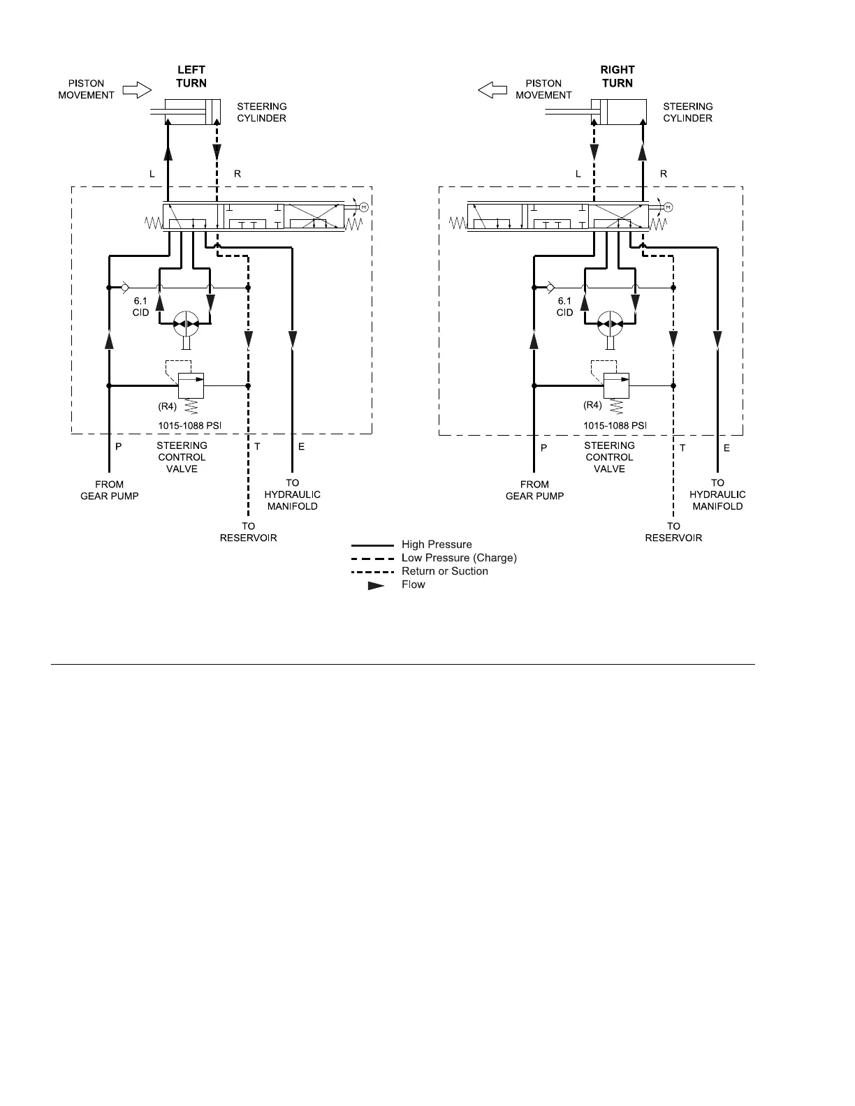
Figure25
SteeringCircuitDiagram
Gearpump(P2)suppliesoilowforthesteeringcircuitandliftcircuit,andalso
providesaconstantsupplyofchargeoiltotheclosedlooptractioncircuit.The
pumpoutputowstothesteeringcontrolvalvebeforesupplyingtheliftand
chargecircuitneedssothatthesteeringcircuithaspriority.Thesteeringcircuit
pressureislimitedto7,000to7,500kPa(1,015to1,088psi)byreliefvalve(R4)
locatedinthesteeringcontrolvalve.
Whenthesteeringwheelisnotbeingturnedandtheengineisrunning(hydraulic
pumpinputshaftrotating),gearpumpowentersthesteeringcontrolvalveat
thePportandby-passestherotarymeterandsteeringcylinder.Flowleaves
thesteeringcontrolvalvethroughtheEportandisdirectedtotheliftmanifold
tosupplytheliftandchargecircuits.
LeftTurn
Whenaleftturnismadewiththeenginerunning,theturningofthesteering
wheelpositionsthesteeringcontrolspoolvalvesothattheowgoesthroughthe
bottomofthespool.FlowenteringthesteeringcontrolvalveatthePportpasses
throughtherotarymeterandisdirectedouttheLport.Pressureretractsthe
steeringcylinderforaleftturn.Therotarymeterensuresthattheuidowtothe
cylinderisproportionaltoamountofsteeringwheelrotation.Theuidleavingthe
HydraulicSystem:HydraulicFlowDiagrams
Page5–16
Groundsmaster
®
3200,3300and3310
19240SLRevA