Fuses
g305067
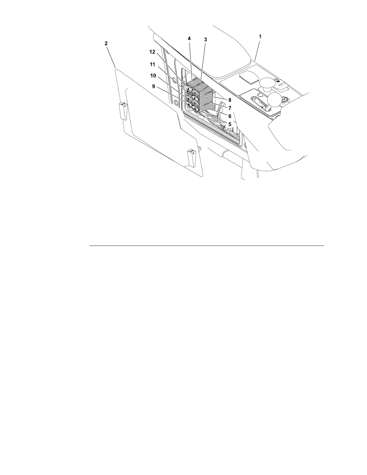
Figure78
1.Operator’scontrolconsole
7.FuseFB1-F3
2.Accesscover8.FuseFB1-F4
3.Fuseblock19.FuseFB2-F1
4.Fuseblock210.FuseFB2-F2
5.FuseFB1-F111.FuseFB2-F3
6.FuseFB1-F212.FuseFB2-F4
Mostoftheindividualcontrolcircuitsareprotectedbyavarietyoffusesfound
inthemainfuseblockslocatedintheoperator’scontrolconsole.Anumberof
in-linefusesareintegratedintothemachinewireharness;refertoIn-lineFuses
(page6–13).Machineswithacabincludeadditionalcontrolcircuitsprotectedby
fusesfoundinthecabpowersupplyharnessandinthecabfuseblocklocated
inthecabcontrolpanel.Machineswithoptionallightingkitsincludeadditional
controlcircuitsprotectedbyfusesfoundinafuseblocklocatedinthesteering
columncontrolpod,andinthelightingkitwireharness.RefertoAppendixA
(pageA–1)forspeciccircuitinformation.
FuseIdenticationandFunction
MainFuseBlocks
•FB1-F1:(models31900and31901=20Amp,models31902,31903,31907
and31909=15Amp)suppliesunswitchedpowertothekeyswitch.
•FB1-F2:(models31900and31901=15Amp,models31902,31903,31907
and31909=10Amp)suppliesswitchedpowertotheTDMcontrollerKey
Startcircuitandthestartinterlockrelayswitch.
•FB1–F3:(10Amp)suppliesswitchedpowertotheTDMcontrollerKeyRun
circuit.
•FB1–F4:(15Amp)suppliesswitchedpowertotheTDMcontrollerlogicand
outputcircuits.
•FB2–F1:(20Amp)suppliesswitchedpowertotheglowrelaycoil,the
alternatorIGcircuit,thefusesFB1–F3andFB1–F4,thecuttingunitraise
limitswitch,thetractionneutralswitch,theexpansionport,thetelematics
ElectricalSystem:TestingtheElectricalComponents
Page6–12
Groundsmaster
®
3200,3300and3310
19240SLRevA