HydraulicManifold
g303280
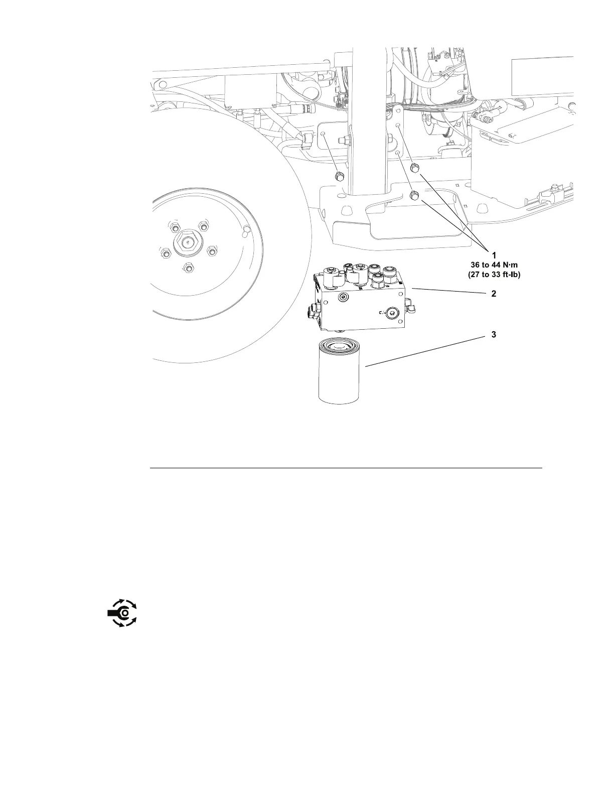
Figure61
1.Capscrew(3each)3.Hydraulicuidlter
2.Hydraulicmanifoldassembly
RemovingtheHydraulicManifold
RefertoFigure61forthisprocedure.
1.Parkthemachineonalevelsurface,lowerthecuttingunit(orattachment),
engagetheparkingbrake,setthekeyswitchtotheOFFpositionandremove
thekeyfromthekeyswitch.
2.Removethefueltankfromthemachine;refertoRemovingandInstalling
theFuelT ank(page4–18).
3.Emptythehydraulictankthroughthedrainplugatthebottomofthetank.
UseanewO-ringandinstalltheplugwhennishedtopreventcontamination
fromenteringthehydraulicsystem.Tightenthedrainplugfrom18to19
N·m(155to171in-lb).
4.Removeanddiscardthehydraulicuidlter.
5.ReadandadheretotheinformationprovidedinGeneralPrecautionsfor
RemovingandInstallingtheHydraulicSystemComponents(page5–52).
6.Cleanthehydraulictubeends,hoseends,andttingsonthemanifoldto
preventcontaminantsfromenteringintothehydraulicsystem.
HydraulicSystem:ServiceandRepairs
Page5–88
Groundsmaster
®
3200,3300and3310
19240SLRevA