HydraulicSolenoidValveCoils
g304231
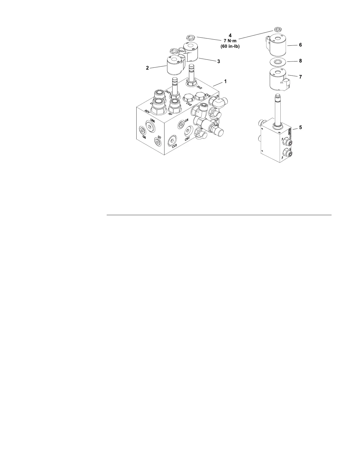
Figure106
1.Mainhydraulicmanifold5.Auxiliaryhydraulicvalvemanifold(optional)
2.ValveSV1coil(raise)6.AuxiliaryvalvecoilS1
3.ValveSV2coil(lower)7.AuxiliaryvalvecoilS2
4.Coilnut8.Coilspacer
Electriccoilactuatedhydraulicvalvesareusedonthemainmanifoldandthe
optionalAuxiliaryHydraulicValvemanifold.Whenthecoilorthecoilrelayis
energizedbytheTDM,thehydraulicvalveshiftstocontrolhydraulicow.
Toassistintroubleshooting,identicalreplaceablesolenoidcoilscanbe
exchanged.Iftheproblemfollowsthecoil,thecoilislikelyatfault.Iftheproblem
remainsunchanged,somethingotherthanthecoilisthelikelyproblemsource
(e.g.switch,circuitwiring,hydraulicproblem).
TestingtheHydraulicSolenoidValveCoils
Typically,afailedsolenoidcoilwilleitherbeshorted(verylowornoresistance)
oropen(inniteresistance).
1.Locatethehydraulicsolenoidvalvecoiltobetestedanddisconnectthewire
harnessconnectorfromthecoil.Checktheharnessconnectorsfordamage
orcorrosionandcleanorrepairifnecessary.
Note:Priortotakingsmallresistancereadingswithadigitalmultimeter,short
themetertestleadstogether.Themeterwilldisplayasmallresistancevalue
(usually0.5ohmsorless).Thisresistanceisduetotheinternalresistanceof
themeterandtestleads.Subtractthisvaluefromthemeasuredvalueofthe
componentyouaretestingtoobtainanaccuratereading.
2.Usingamultimeter(ohmssetting),measuretheresistancebetweenthetwo
(2)connectorterminalsonthesolenoidcoil.Theresistanceforthesolenoid
coilsisidentiedbelow:
A.ThecoilsofsolenoidvalvesSV1andSV2onthemainhydraulicmanifold
arethesame.Resistanceofthesecoilsshouldbeapproximately8.8
ohmswhentestedat20°C(68°F).
Groundsmaster
®
3200,3300and3310
Page6–59
ElectricalSystem:TestingtheElectricalComponents
19240SLRevA