HydraulicManifoldService(continued)
g297319
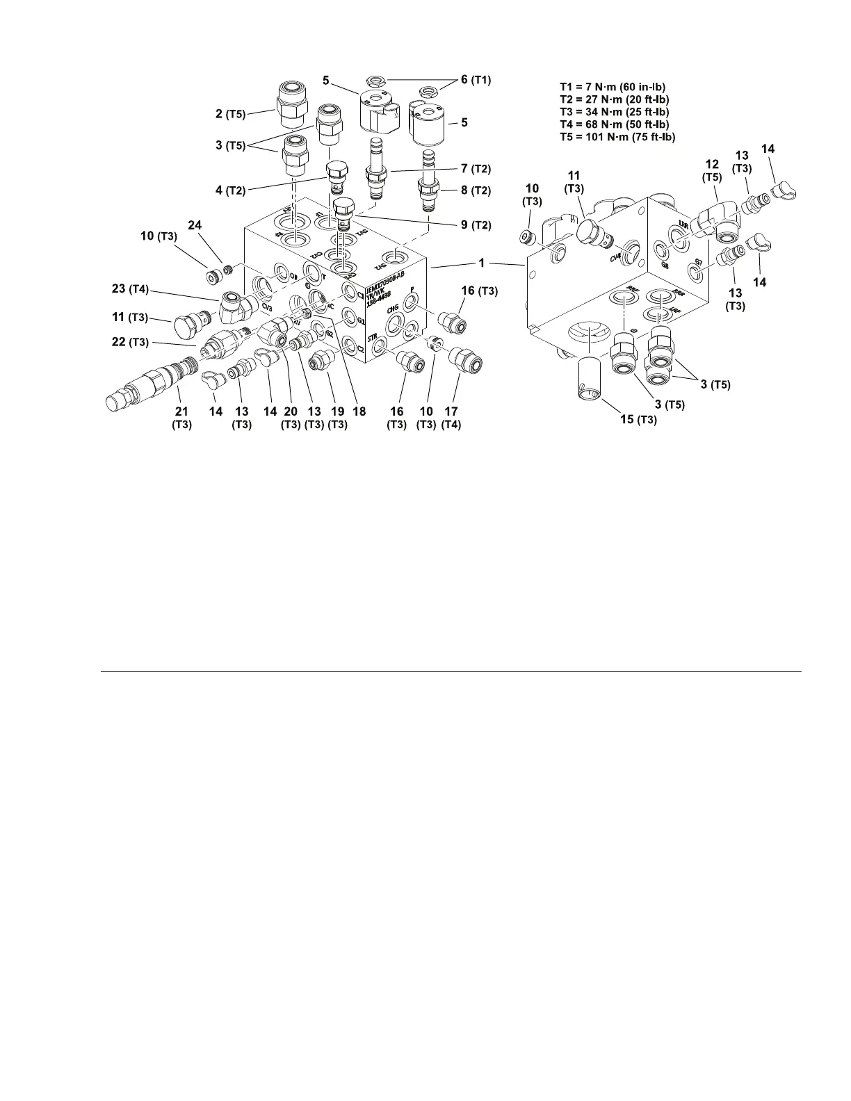
Figure63
(4WDManifold–Models31901/31902/31903/31907/31909)
1.Manifoldblock9.Checkvalve–CV117.Straighttting
2.Straighttting10.#6zero-leakplugwithO-ring(3
each)
18.Checkorice–0.100inch–C1
3.Straighttting(5each)
11.Checkvalve–CV3/CV419.Straighttting
4.Checkvalve–CV212.Elbowtting20.Elbowtting
5.Solenoidcoil(2each)13.Diagnostictting(4each)21.Logiccartridge–LC
6.Coilnut(2each)14.Cap(4each)22.Bi-directionalreliefvalve–CRV
7.Solenoidvalve–SV1
15.Filternipple
23.Elbowtting
8.Solenoidvalve–SV216.Straighttting(2each)24.Controlorice–0.040inch–OR
Theportsonthemanifoldaremarkedforeasyidenticationofcomponents
andconnections.Example:Pisthepressureconnectionportfromthesteering
controlvalveandSV1isthelocationforthelift/lowersolenoidvalve;refertothe
hydraulicschematicinAppendixA(pageA–1)toidentifythefunctionofthe
hydrauliclinesandcartridgevalvesateachport.
Forcartridgevalveserviceprocedures,refertoCartridgeValveService(page
5–93).
Thehydraulicmanifoldincludeseveralzero−leakplugs.Theseplugshavea
taperedsealingsurfaceontheplugheadthatisdesignedtoresistvibration
inducedplugloosening.Thezero−leakplugsalsohaveanO−ringasa
secondaryseal.Ifremovingazero−leakplugisnecessary,lightlyraptheplug
headusingapunchandhammerbeforeusingahexwrenchtoremovetheplug:
theimpactwillallowplugremovalwithlesschanceofdamagetothesockethead
oftheplug.Tightentheplugstothetorquevalueprovided.
Groundsmaster
®
3200,3300and3310
Page5–91
HydraulicSystem:ServiceandRepairs
19240SLRevA
 Loading...


