RemovingtheSteeringCylinder(continued)
8.Ifthehydraulicttingsaretoberemovedfromthecylinder,markthetting
orientationforassemblypurposesandremovethettingsfromthecylinder.
DiscardtheO-ringsfromthettings.
InstallingtheSteeringCylinder
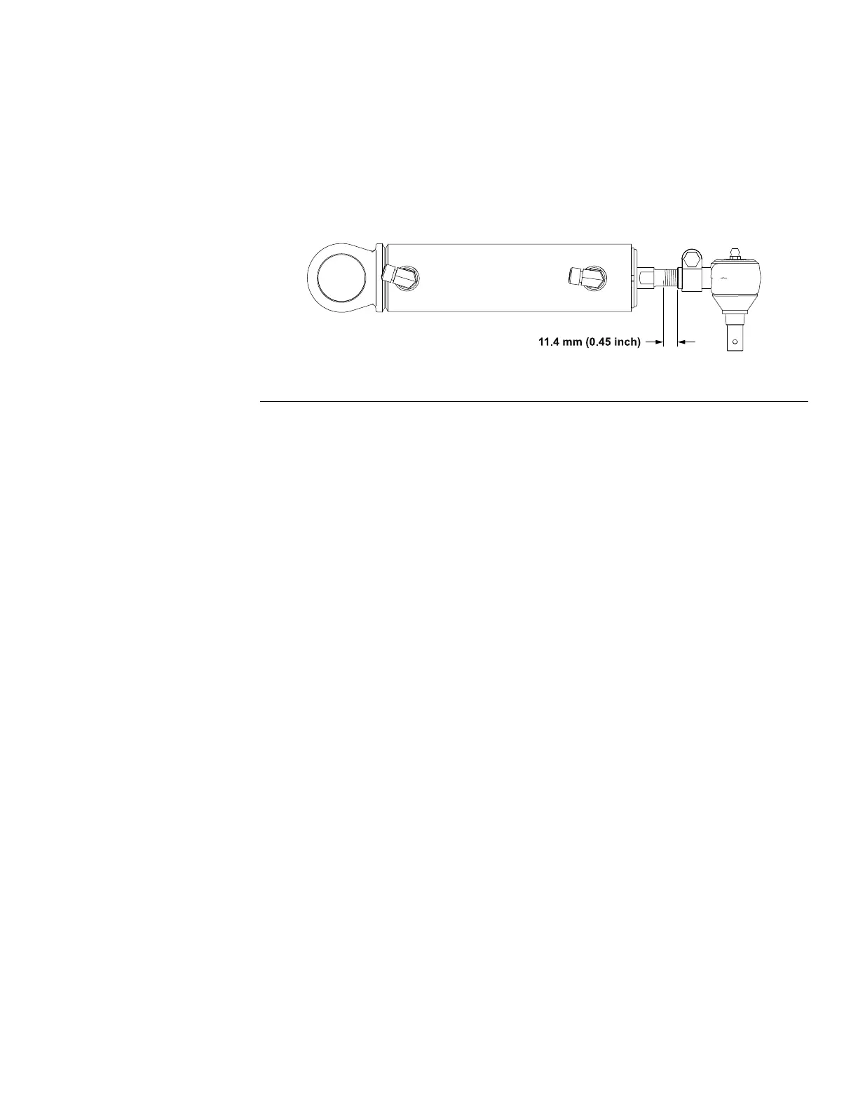
RefertoFigure66forthisprocedure.
1.Ifpreviouslyremoved,pressthebarrelendballjointintothecylinderand
installtherodendballjointatthepositionshown.
g314860
Figure67
2.Ifthehydraulicttingswereremovedfromthecylinder,lubricatenewO-rings
withcleanhydraulicuid,positiontheO-ringstothettings,andinstallthe
ttingsinthemarkedorientation;refertoInstallingtheHydraulicFittings
(SAEStraightThreadO-RingFittings)(page5–9).
3.Installthesteeringcylinderinthemachinewiththepreviouslyremoved
fasteners.Securetheslottednutwithanewcotterpin.
4.Removethecapsandplugsthenconnectthehydraulictubestothecylinder
ttings;refertoInstallingHydraulicHosesandTubes(O-RingFaceSeal
Fitting)(page5–7).
5.Lubricatethecylinderballjointgreasettings.
6.Operatethesteeringcylinder.Checkforhydraulicleaksandcorrectif
necessary.
7.Adjustthesteeringcylinderrodlengthandthesteeringstopbolts:
A.Loosenthejamnutsoneachsteeringstopboltandturnthestopbolts
intotheaxleasfaraspossible.
B.Starttheengineandturnthesteeringwheeltofullleftturn.Setthekey
switchtotheOFFposition.
C.Loosenthesteeringcylinderrodendballjointclampandturnthesteering
cylindershaftinoroutuntilthegapbetweentheleftdraglinkandthe
steeringstopboltis1.5to4.6mm(0.60to0.18inch).
Groundsmaster
®
3200,3300and3310
Page5–99
HydraulicSystem:ServiceandRepairs
19240SLRevA
 Loading...


