TDMDisplay/Controller(continued)
TDMDisplay/ControllerInputs(continued)
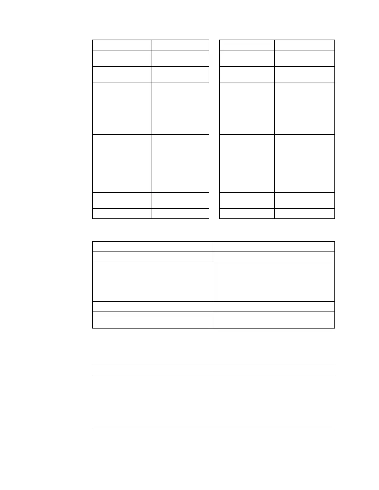
INPUTNUMBER
DESCRIPTION
INPUTNUMBER
DESCRIPTION
IN1
KeySwitch–Start
IN7TractionNeutral
Switch
IN2
PTOSwitch
AIN1
CuttingUnitHighTrim
HeightSwitch
IN3
CuttingUnitLift
LowerSwitch–
Lower
AIN2Model31900,31901,
31907and31909=
OilPressureSwitch
Model31902and
31903=Throttle
Switch–Decrease
Speed
IN4
CuttingUnitLift
LowerSwitch–Lift
AIN3Model31900,31901,
31907and31909
=EngineCoolant
TemperatureSender
Model31902and
31903=Throttle
Switch–Increase
Speed
IN5
ParkingBrakeSwitch
AIN4
DisplayScreenSelect
Button
IN6
SeatSwitch
TDMDisplay/ControllerOutputs
OUTPUTNUMBERDESCRIPTION
OUT1PTOClutch
OUT2
Model31900,31901,31907and31909=
StartInterlockRelay(coil),FuelPump,and
FuelStopSolenoid(holdcoil)
Model31902and31903=StartInterlockRelay
(coil)andEngineECU(startsignal)
OUT3HydraulicSolenoidValveSV1(cuttingunitlift)
OUT4HydraulicSolenoidValveSV2(cutting
unitlower)
ThemachineelectricalschematicandwireharnessdrawingsinAppendix
A(pageA–1)canbeusedtoidentifypossiblecircuitproblemsbetweenthe
controllerandtheinputoroutputdevices.
IMPORTANT
Whentestingforwireharnesscontinuityattheconnectorfor
thecontroller,takecaretonotdamagetheconnectorpinswith
multimetertestleads.Ifconnectorpinsareenlargedordamaged
duringtesting,connectorrepairmaybenecessaryforproper
machineoperation.
ElectricalSystem:TestingtheElectricalComponents
Page6–20
Groundsmaster
®
3200,3300and3310
19240SLRevA
 Loading...


