AdjustingtheCuttingUnitHighTrimHeightSwitch(continued)
g306186
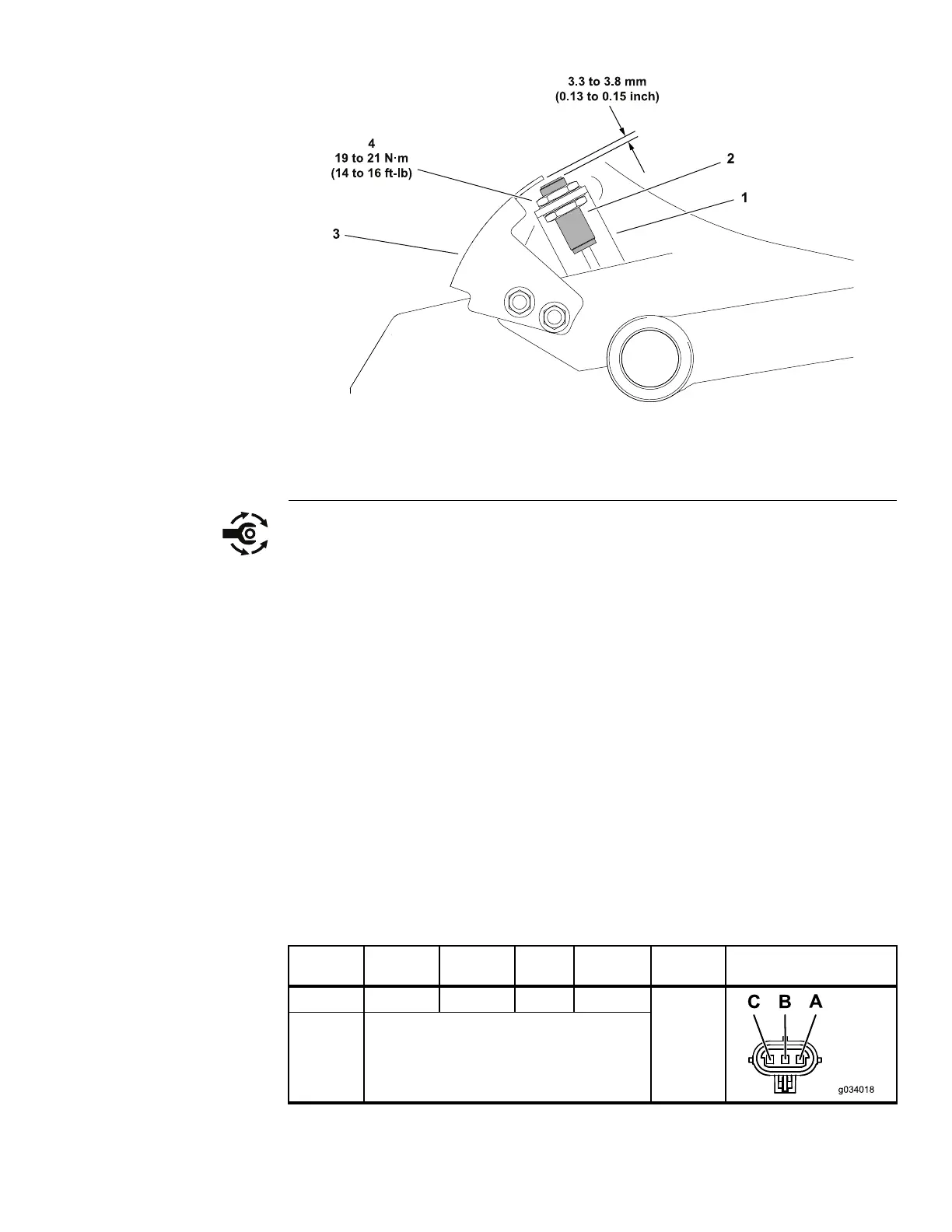
Figure92
1.Switchbracket(onframe)3.Sensingplate(onliftarm)
2.Hightrimheightswitch
4.Jamnut(2each)
3.Ifnecessary,loosenthelocknutssecuringtheswitchtotheswitchbracket
andsettheswitchsothecorrectclearanceexistsbetweenthetargeteye
andthesensingplate.Tightentheswitchlocknutsfrom19to21N·m(14
to16ft−lb).Re-checktheswitchtosensingplateclearanceandadjust
ifnecessary.
TestingtheCuttingUnitHighTrimHeightSwitch
Thecuttingunithightrimheightswitchanditscircuitwiringcanbetestedusing
theTDMdisplay/controller;refertoUsingtheTDMDisplay/ControllerScreens
forTroubleshooting(page3–12).Iftestingdeterminesthattheswitchandcircuit
wiringarenotfunctioningcorrectly,proceedwiththefollowingtestprocedure:
1.Parkthemachineonalevelsurface,lowerthecuttingunit(orattachment),
engagetheparkingbrake,setthekeyswitchtotheOFFpositionandremove
thekeyfromthekeyswitch.
2.Ensurethatthehightrimheightswitchisproperlyadjusted;refertoAdjusting
theCuttingUnitHighTrimHeightSwitch(page6–34).
3.Disconnectthehightrimheightswitchfromthemachinewireharness.
Checktheharnessconnectorsfordamageorcorrosionandcleanorrepair
ifnecessary.Useamultimeter(ohmssetting)tocheckthemachinewire
harnessconnector.
LocationHarness
Connector
Pin
Wire
Color
Expected
Reading
ConnectorGraphic
1MainP102
C
Black
2
ChassisGround
Lessthan
2ohms
Groundsmaster
®
3200,3300and3310
Page6–35
ElectricalSystem:TestingtheElectricalComponents
19240SLRevA
 Loading...


