TestingtheCANbusTerminatorResistors(continued)
resistorandtheresistorholderfordamageorcorrosionandcleanorrepair
ifnecessary.
Note:Theinsulatorwedgeintheexternalterminationresistorisblue
foridenticationpurposes.Therealsoisacenterkeywaytopreventthe
terminationresistorfrompluggingintothewrongwireharnessconnector.
LocationHarness
Connector
Pin
Wire
Color
Expected
Reading
ConnectorGraphic
1A
2
CANbus
Terminator
Resistor
Resistor
at
connector
P35or
P111
B
N/A
120
ohms
4.Iftestingdeterminestheexternalterminationresistorisfaulty,replacethe
resistor.
5.Aftertestingiscomplete,makesuretheexternalterminatorresistorisfully
installedintotheconnectorandsecuredtothewireharness.
6.Installtheoperator’sconsolecoversifpreviouslyremoved.
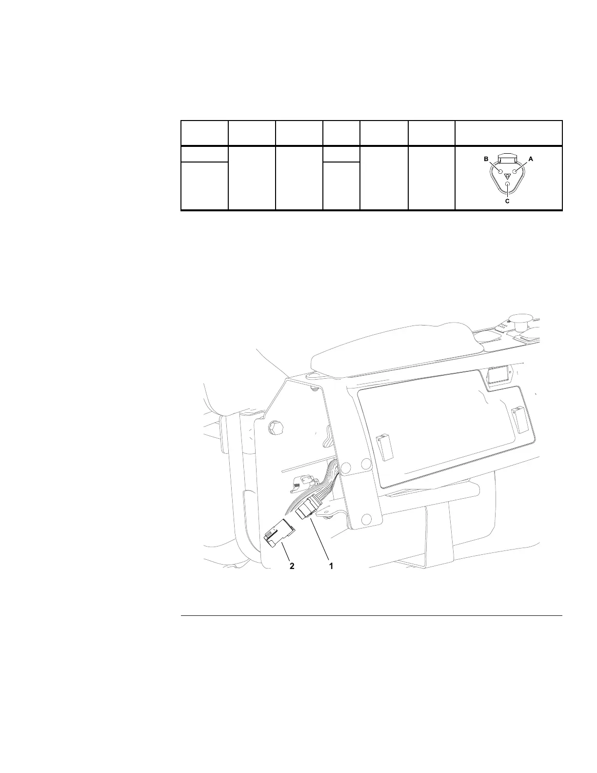
InternalResistors
g305815
Figure105
1.YanmarSA-Dconnector2.Cover
1.Parkthemachineonalevelsurface,lowerthecuttingunit(orattachment),
engagetheparkingbrake,setthekeyswitchtotheOFFpositionandremove
thekeyfromthekeyswitch.
2.Removetheoperator’sconsolecovers;refertoRemovingandInstallingthe
Operator’sConsoleCovers(page7–23).
3.DisconnecttheexternalCANbusterminatorresistorfromthemachinewire
harnessatthefrontoftheoperator’sconsole.
Groundsmaster
®
3200,3300and3310
Page6–57
ElectricalSystem:TestingtheElectricalComponents
19240SLRevA