3-46 Phaser 7750 Printer Service Manual
Transmissive Sensor Procedure
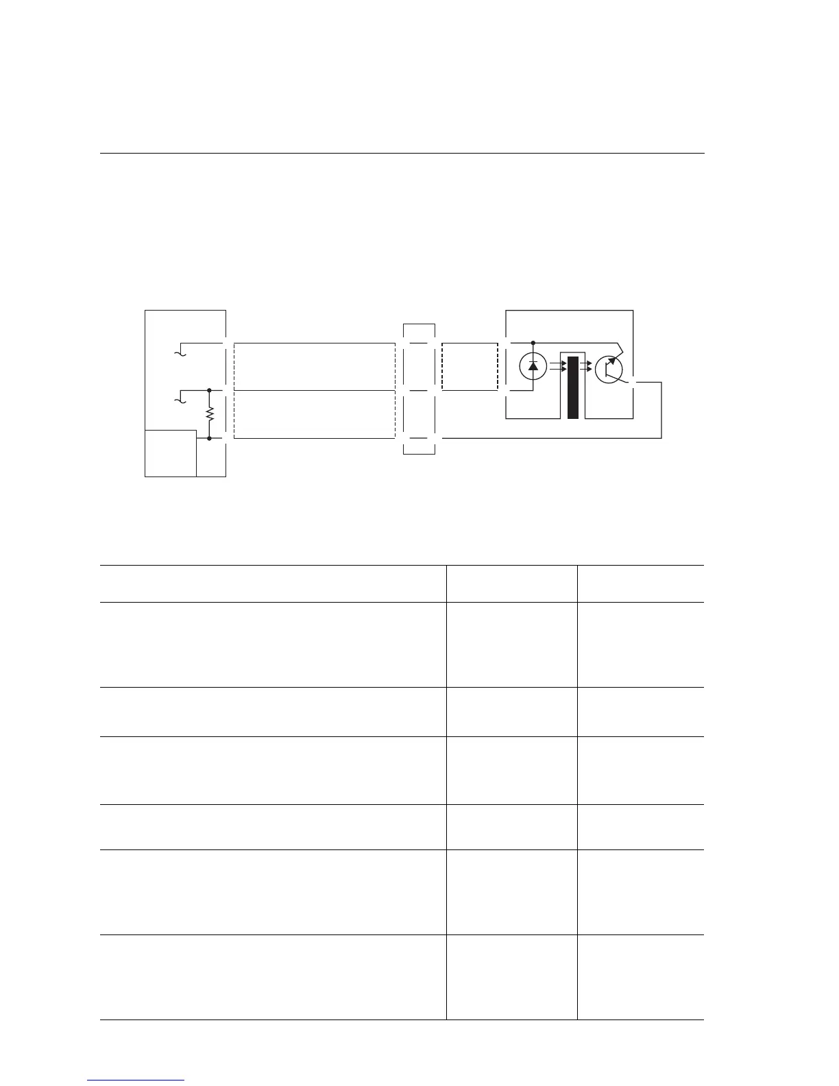
Refer to the following figure during this procedure.
Troubleshooting References
Applicable Parts Wiring and Plug/Jack Map References
■ Transmissive Sensor
■ Engine Control Board
Troubleshooting Procedure
Step Actions and Questions Yes No
1
1. Enter service diagnostics and run the
Transmissive Sensor test.
2. Does the sensor change state from L
to H when blocked?
Replace the
sensor.
Go to step 2.
2
1. Remove the sensor connector.
2. Does the sensor now change state?
Replace the
sensor.
Go to step 3.
3
1. Check for a short between sensor Pin
2 and engine control board Pin 8.
2. Is there a short?
Replace the wiring
harness.
Go to step 4.
4
1. Is there +5 VDC between sensor Pin2
and ground?
Go to step 6. Go to step 5.
5
1. Check the wiring between sensor Pin 2
and engine control board Pin 8 for an
open or poor circuit.
2. Is the wiring OK?
Replace the
affected board.
Repair or replace
the wiring
harness.
6
1. Check the wiring to Pin 4 and sensor
Pin 1 and Pin 5 to sensor Pin 3 for an
open or poor circuit.
2. Is the wiring OK?
Replace the
affected board.
Replace the
wiring harness.
7750-342
76
CONTROL
LOGIC
PWB
PL
DC ROM
DC ROM
+5VDC
+5VDC
4
5
3
1
2
8
DOUBLE
PLUG
SENSOR
PL
YEL

 Loading...


