Service Parts Disassembly 8-49
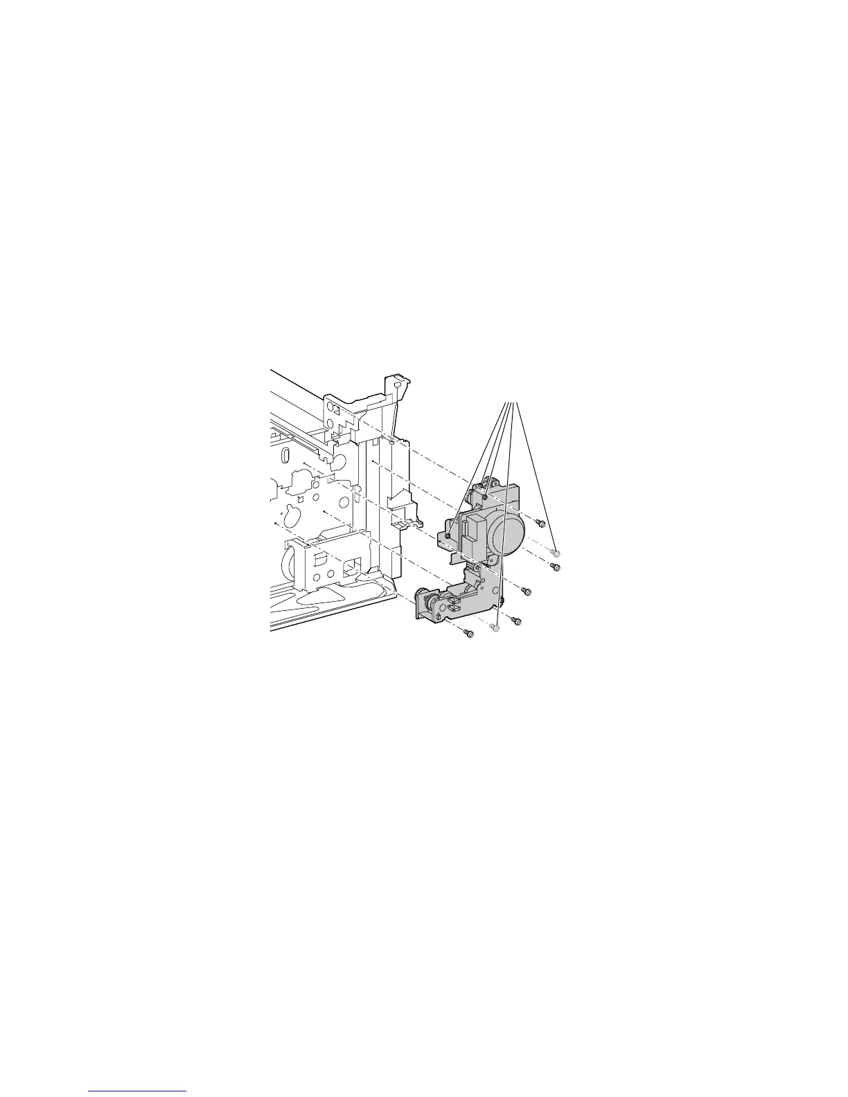
Main Drive Assembly
1. Remove the fuser.
2. Remove Tray 1 /(MPT), see page 8-9.
3. Remove the T2 high-voltage power supply, see page 8-47.
4. Disconnect the wiring harness.
Caution
There are 5 brass screws that hold the main drive assembly together. DO
NOT REMOVE these screws.
5. Remove the 5 black screws that secure the complete main drive assembly to the
printer frame.
6. Lift the complete main drive assembly up and out of the printer.
Replacement Procedures
Note
When reinstalling, rotate the main drive to ensure the gears move freely.
Remove the Fuser unit to give better visibility.
1. As the main drive assembly is being installed into position, make sure the gears
are meshed completely with the mating gears by slightly rotating the main motor
until the main motor bracket seats without stress, and is flat against the frame.
2. Rotate the main drive after installing the assembly to ensure it rotates freely, and
ensure it is FLAT against the frame.
Caution
It is easy to pinch or short wires under the main drive assembly bracket.
3. Make sure that the red transfer roller wire is connected near the right side of the
main drive assembly to its mating connector on the frame.
7750-121
Do NOT remove
these 5 screws

 Loading...


